
Magnetic resonance imaging method and application based on spin-locking technology to detect oscillating magnetic field

A technology of magnetic resonance imaging and locking technology, which is applied in the size/direction of the magnetic field, the use of the nuclear magnetic resonance imaging system for measurement, magnetic resonance measurement and other directions, which can solve the problems of interference and no positive results, and achieve the effect of improving the sensitivity

Active Publication Date: 2017-10-31
PEKING UNIV
View PDF5 Cites 0 Cited by
  • Summary
  • Abstract
  • Description
  • Claims
  • Application Information

AI Technical Summary

Problems solved by technology

However, such detection methods have not yielded consistent positive results
The main reasons are that the contrast between the magnetic field caused by neuron discharge and the change of BOLD magnetic field is smaller, and there are: 1) the interference of BOLD signal during the imaging time; The signals cancel each other out; 3) The spatial arrangement of neurons causes the collective firing of different neurons to cancel each other out
The first two reasons are insurmountable by GE-EPI technology itself

Method used

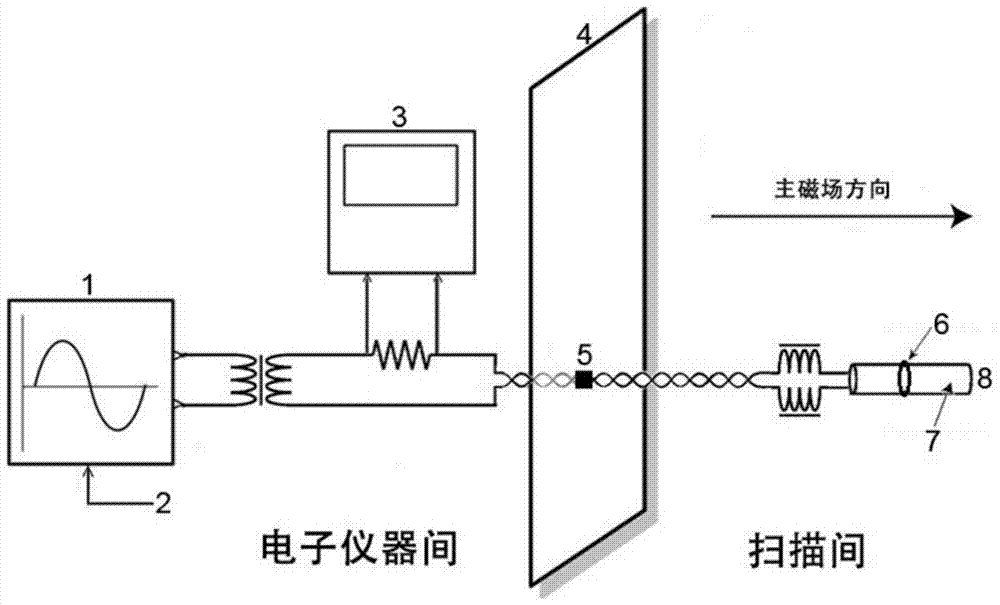
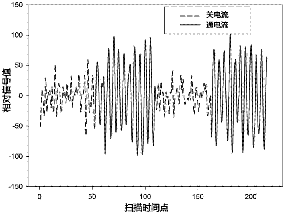

Image

  • Magnetic resonance imaging method and application based on spin-locking technology to detect oscillating magnetic field
  • Magnetic resonance imaging method and application based on spin-locking technology to detect oscillating magnetic field
  • Magnetic resonance imaging method and application based on spin-locking technology to detect oscillating magnetic field

Examples


Embodiment Construction

[0029] In the following description, numerous specific details are given to facilitate a more thorough understanding of the present invention to those skilled in the art. It should be understood that what is disclosed herein is only a representative preferred embodiment. Apparently, the present invention is not limited to any specific structures, functions, devices and methods described herein, and may also have other implementations or combinations of other implementations. The number of elements described in the present invention is also conceivable in plural unless expressly limited to a singular number. In addition, in order to avoid confusion between other examples and the present invention, some technical features and details well known in the art have not been described.

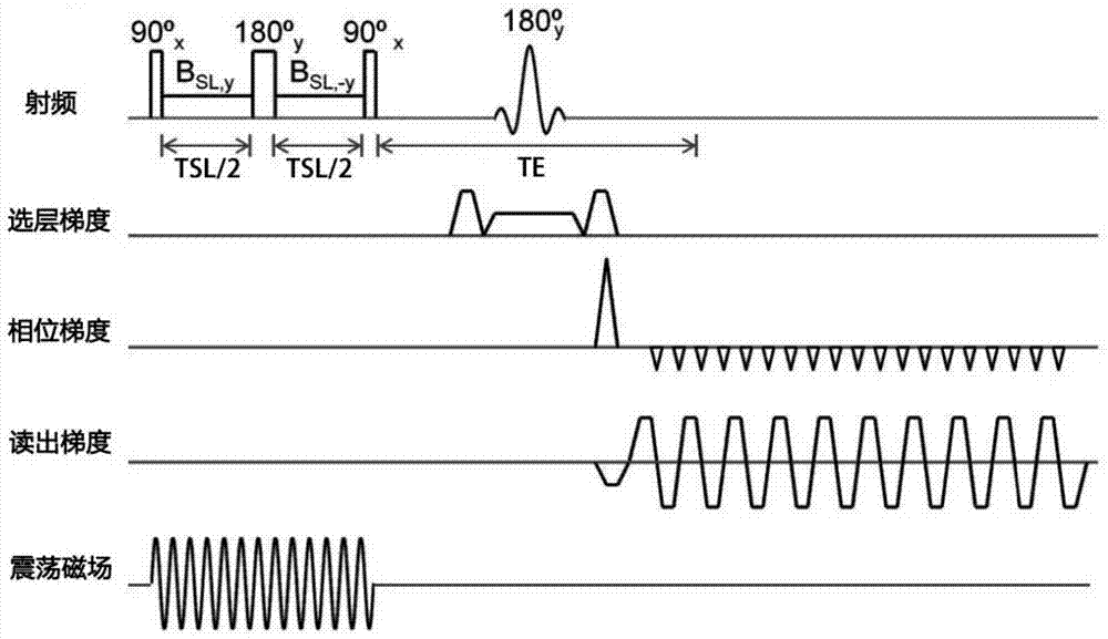
[0030] figure 1 It is a schematic diagram of the SLOE sequence of the present invention. Such as figure 1As shown, the SLOE sequence consists of a spin-lock preparation pulse sequence and an echo-...


PUM


Abstract

The invention discloses a magnetic resonance imaging method used for oscillatory magnetic field detection and based on a spin-locked technology and application, and names as Spin-Locked Oscillatory Excitation, SLOE. SLOE comprises a spin-locked preparation sequence insensitive to main magnetic field and radio frequency field inhomogeneity and spin planar echo acquisition. According to the method, after the spin-locked preparation sequence, any additional excitation pulse is no longer applied, and all acquired signals are magnetization vector signals deflected by oscillatory magnetic field excitation. In a data processing process, due to the fact that the initial phase of oscillatory current scanned every time is random, the fluctuation of a check signal time sequence is statistically used to detect an activation signal. According to the invention, defects of conventional neuronal discharge sequence detection are solved; the sensitivity of tiny oscillatory magnetic field detection is greatly improved; neuronal discharge can be successfully detected through magnetic resonance detection in vivo; and technological innovation in the field can be promoted.

Description

technical field [0001] The invention relates to the field of magnetic resonance imaging, and relates to a magnetic resonance imaging method and application for detecting an oscillating magnetic field based on a spin-locking technology, in particular to an application of the magnetic resonance method for neuron current magnetic resonance imaging. Background technique [0002] The functional Magnetic Resonance Imaging (fMRI) method based on Blood-Oxygen-Level-Dependence (BOLD) has achieved unprecedented development since Ogawa et al. BOLD fMRI has now become an important research tool in cognitive neuroscience. However, the BOLD principle is mainly based on the change of the magnetization properties of deoxyhemoglobin based on the hemodynamic response, and the hemodynamic response itself is a very slow process (on the order of 1s) in the living body, and its speed is much lower than that of the nervous system. Therefore, BOLD fMRI detection of neural activity has a relatively...

Claims


Application Information

Patent Timeline
Patent Type & Authority Patents(China)
IPC IPC(8): G01R33/54G01R33/561G01R33/24A61B5/055
Inventor 高家红江夏盛经纬柴玉辉
Owner PEKING UNIV
Learn More