Device for encoding motion picture signals and encoding method

A moving image and image coding technology, applied in image communication, digital video signal modification, television, etc., can solve problems such as deterioration

Inactive Publication Date: 2001-10-10
PANASONIC CORP
View PDF0 Cites 2 Cited by
  • Summary
  • Abstract
  • Description
  • Claims
  • Application Information

AI Technical Summary

Problems solved by technology

[0011] In this way, the picture quality when a transmission error occurs in the first picture is significantly worse than the picture quality when the concealment process is performed in the case of the previous coded picture
In addition, there is a problem that, since the motion compensation prediction method is used, the image quality deterioration in the first picture propagates over time after the second picture

Method used


Image

  • Device for encoding motion picture signals and encoding method
  • Device for encoding motion picture signals and encoding method
  • Device for encoding motion picture signals and encoding method

Examples


Embodiment 1

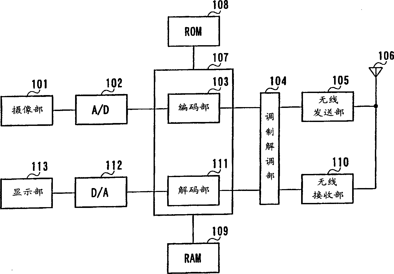
[0022] figure 1 is a block diagram showing the structure of a wireless communication device including an encoding device according to an embodiment of the present invention. Here, the wireless communication device refers to a communication terminal device such as a base station device or a mobile station in a digital wireless communication system. In addition, the wireless communication terminal device may be a mobile terminal, or may be connected to a computer and used.

[0023] In this wireless communication device, an image is captured by an imaging unit 101 such as a video camera at the transmitting end, and is output to an A / D converter 102 as an image signal. In the A / D converter 102 , the image signal is converted into a digital audio signal, and output to the encoding unit 103 . The encoding unit 103 performs image encoding processing on the digital audio signal, and outputs the encoded information to the modem unit 104 . The modem unit 104 digitally modulates the c...

Embodiment 2

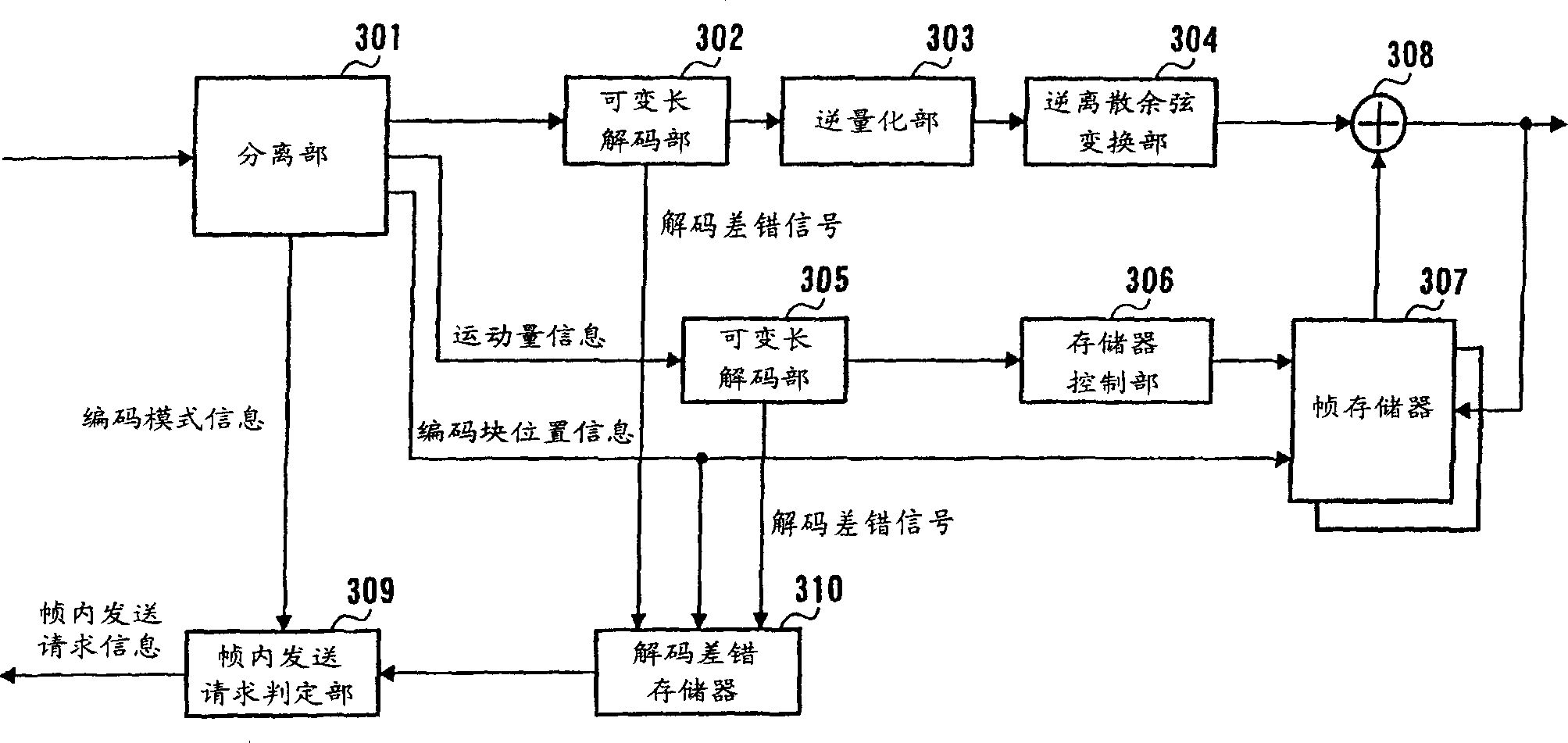
[0073] image 3 It is a block diagram showing the structure of a decoding device corresponding to an encoding device according to an embodiment of the present invention.

[0074] exist image 3 Among them, the received signal is sent to the separation unit 301, where it is separated into Huffman codes of DCT coefficients, Huffman codes of motion information, coding block position information, and coding mode information, and sent to respective processing units. Specifically, the DCT coefficients are sent to the variable length decoding unit 302, the motion amount information is sent to the variable length coding unit 305, the coded block position information is sent to the frame memory 307 and the decoding error memory 310, and the coding mode information is sent to Intra-frame transmission request determination unit 309 .

[0075] The DCT coefficients decoded by the variable length decoding unit 302 are sent to the inverse quantization unit 303 to be dequantized. The dequa...


PUM


Abstract

A picture counter 205 counts and outputs the number of pictures input from the beginning of communication. A coding controlling section 206 outputs coding mode information for controlling a coding apparatus to perform intra-coding when a counted value of the picture counter 205 is equal to or less than a predetermined value (N), and outputs coding mode information for motion compensation prediction system when the counted value is more than N. Moreover, when the counted value is equal to and less than (N-1), the coding controlling section 206 outputs a signal for controlling a quantization section 210 to make the value of a quantization parameter large to the quantization section 210, and when the counted value is N, the coding controlling section 206 outputs a signal for controlling the quantization section 210 to make the quantization parameter small to the quantization section 210. A switch 207 is switched to "0" in case of the intra-coding and is switched to a frame memory 203 in case of the compensation prediction system in conformity with a signal of the coding controlling section 206.

Description

technical field [0001] The present invention relates to a coding device and coding method for digital moving picture signals used in videophones, video conferencing, etc., and particularly to a coding device and coding method for digital moving picture signals in video communication on a transmission line where transmission errors occur, as well as a decoding device and decoding method. Background technique [0002] As a conventional encoding method for digital moving image signals, the encoding method in ITU-T Recommendation (recommendation) H.261 recommended in March, 1993 can be mentioned. A characteristic coding method of H.261 is a motion compensation prediction method. The motion compensation prediction method is specifically performed as follows. [0003] First, the input image frame is compared with the previous coded frame, and the amount of motion therebetween is measured (motion detection). An input image picture is predicted based on the motion amount and the ...

Claims


Application Information

Patent Timeline
Patent Type & Authority Applications(China)
IPC IPC(8): H04N19/107H04N19/164H04N19/176H04N19/423H04N19/50H04N19/503H04N19/51H04N19/61H04N19/625H04N19/65H04N19/85H04N19/89H04N19/895H04N19/91H04N21/6377H04N21/658
CPCH04N19/00781H04N19/00218H04N19/00939H04N19/00133H04N19/0003H04N7/5086H04N19/00096H04N7/3072H04N19/0009H04N21/658H04N19/00933H04N19/00212H04N21/6377H04N7/502H04N19/00266H04N19/159H04N19/172H04N19/134H04N19/61H04N19/107H04N19/124H04N19/126H04N19/157H04N19/89H04N19/895H04N19/105H04N19/51
Inventor 井村康治
Owner PANASONIC CORP
Why Eureka
Try Eureka