Image coding apparatus and image coding method

An image coding and coding technology, applied in the field of image coding technology, can solve problems such as increased frame rate and frame interval, deteriorated image quality, and inflexible actions

Inactive Publication Date: 2008-11-12
PANASONIC CORP
View PDF8 Cites 0 Cited by
  • Summary
  • Abstract
  • Description
  • Claims
  • Application Information

AI Technical Summary

Problems solved by technology

In the example of FIG. 6, the difficult-to-encode frames are consecutive, and since many bits are allocated to the encoding of these frames, the result of gradually reducing the frame rate is that the interval between frames is widened, resulting in an image with slow motion, and the display as an image state of deteriorating quality

Method used


Image

  • Image coding apparatus and image coding method
  • Image coding apparatus and image coding method
  • Image coding apparatus and image coding method

Examples


Embodiment 1

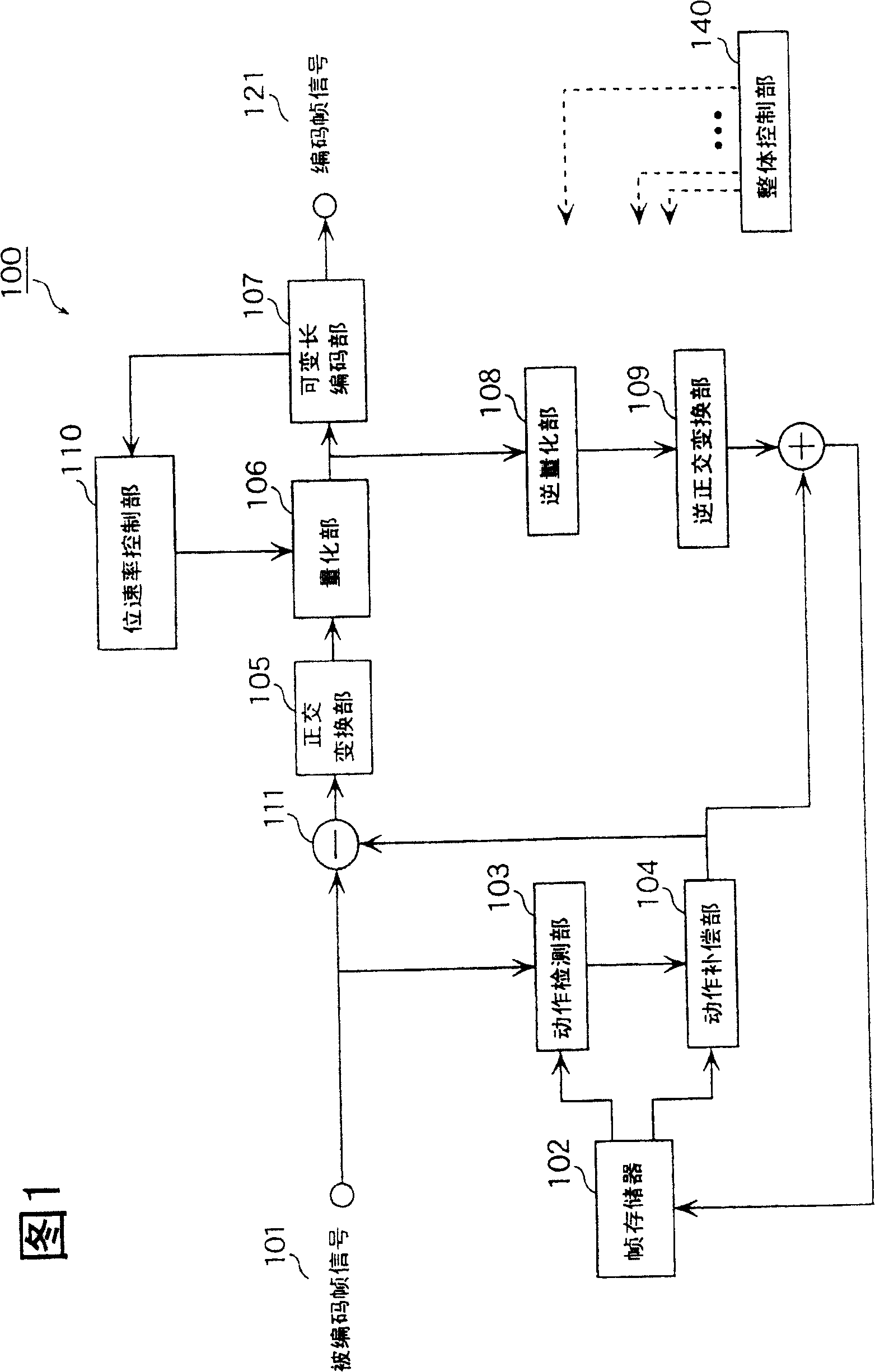
[0081] FIG. 7 is a block diagram showing the functional configuration of the image encoding device 10 according to Embodiment 1. Referring to FIG. The image encoding device 10 can perform encoding for higher-quality image reproduction by keeping the bit rate constant when observed for a predetermined length of time (for example, 1 second) and suppressing local bit rate fluctuations.

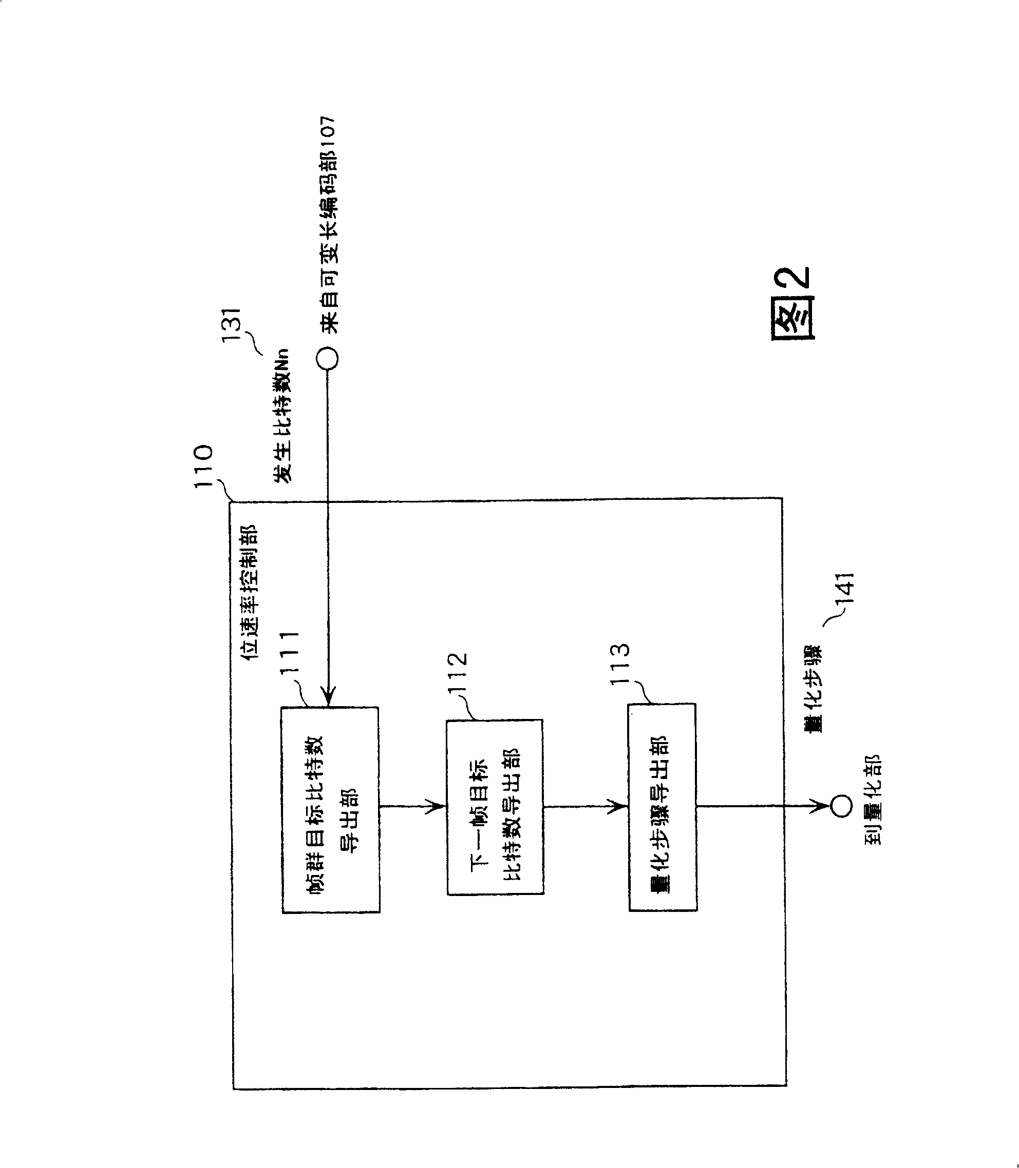
[0082] The image encoding device 10 is composed of a frame memory 102, a motion detection unit 103, a motion compensation unit 104, an orthogonal transformation unit 105, a quantization unit 106, a variable length coding unit 107, an inverse quantization unit 108, an inverse orthogonal transformation unit 109, and a frame extraction unit. Section (interlude section) 20, rate control section 30 and overall control section 40 constitute.

[0083] The frame extracting unit 20 determines encoding / non-encoding of the frame signal 101 to be encoded input within a certain period, and notifies the rate c...

Embodiment 2

[0122] Fig. 19 is a block diagram showing the functional configuration of an image coding device 2100 according to the second embodiment. The image coding apparatus 2100 considers a frame group composed of conventional double-digit frames as shown in FIG. 11 of the first embodiment above, and controls the quantization step or frame extraction to suppress sudden fluctuations in the bit rate or frame rate. Perform high-quality encoding.

[0123] The image coding device 2100 includes a frame extraction unit 2101, a frame memory 102, a motion detection unit 103, a motion compensation unit 104, an orthogonal transformation unit 105, a quantization unit 106, a variable length coding unit 107, a transmission buffer 2108, and an inverse quantization unit 2109. , an inverse orthogonal transform unit 2110 , a difference unit 2111 , an adder 2112 and a frame rate control unit 2113 .

[0124] The frame extraction unit 2101 performs extraction processing on each frame of an image signal i...

Embodiment 3

[0167] Fig. 35 is a block diagram showing the functional structure of the image encoding device 4100 in the third embodiment. The image encoding device 4100 implements more suitable encoding by using the variable bit rate method in the image encoding device 10 of the first embodiment and the variable frame rate method in the image encoding device 2100 in the second embodiment.

[0168] As shown in FIG. 35 , the image encoding device 4100 has the same functional structure as the image encoding device 10 in the first embodiment except for the transmission buffer 2108 , the frame rate control unit 4113 and the frame extraction unit 4116 . In addition, below, the same code|symbol is attached|subjected to the same part as the functional structure in the said Example 1 or Example 2, and description is abbreviate|omitted.

[0169] The frame rate control unit 4113 has only the function of generating extraction information among the functions of the frame rate control unit 2113 of the ...


PUM


Abstract

An image coding technique and image decoding technique capable of preventing degradation of picture caused by the extremely insufficient number of bits to be allocated to residual frames, and enabling coding to reproduce high-quality picture, in a case that scenes difficult to be coded are continued. A deriving part 31 for deriving the frame constellation target number of bits which can be assigned reads out from a memory 36 the total number of bits of frame constellation units to remaining frames, subtracts the generating number of bits used by coding the previous frames and updates, and transmits it to a deriving part 32 for deriving the following frame target number of bits. The deriving part 32 for deriving the following frame target number of bits computes the target number of bits assigned to the following frames based on the remaining frame number in consideration of the received total number of bits and frame rate values Rf. A deriving part 33 for deriving the mean or average frame number of bits computes the mean rate of the number of bits assigned to the former frames. An operation part 34 multiplies the mean rate of the computed number of bits by considered factors, compares this with a target value of the number of bits, and selects a greater one of values and transmits it to a deriving part 35 for a quantization step.

Description

technical field [0001] The present invention relates to an image encoding technique and an image decoding technique, in particular to an image encoding technique using a variable bit rate method or a variable frame rate method. Background technique [0002] Conventionally, a variable bit rate (Variable Bit Rate) method is one of methods for controlling bit rates in image coding technologies such as the MPEG (Moving Picture Expert Group) standard. This is mainly because the bit rate is allowed to locally vary with the complexity of the coded image, and the length of time is specified in order to comply with constraints such as the capacity of the buffer memory that stores the encoded data, or the constraints of the image recording time when recording on the recording medium. (For example, 1 second) The control method suppresses the number of occurrence bits within a certain number. That is, by generating more encoding bits (increasing the bit rate) for difficult-to-encode pi...

Claims


Application Information

Patent Timeline
Patent Type & Authority Patents(China)
IPC IPC(8): H03M3/00H03M7/30H04N7/30G06T9/00
CPCG06T9/00
Inventor 内林京子角野真也高桥润西孝启
Owner PANASONIC CORP
Why Eureka
Try Eureka