Drawing data generation device and image drawing device

A data generation and rendering device technology, which is applied in image data processing, 2D image generation, 3D image processing, etc., can solve problems such as longer rendering time

Inactive Publication Date: 2014-09-17
MITSUBISHI ELECTRIC CORP
View PDF5 Cites 5 Cited by
  • Summary
  • Abstract
  • Description
  • Claims
  • Application Information

AI Technical Summary

Problems solved by technology

[0005] On the other hand, the drawing time of a polygonal model depends on the number of drawing polygons, so when the model is composed of a large number of polygons, the drawing time becomes longer

Method used


Image

  • Drawing data generation device and image drawing device
  • Drawing data generation device and image drawing device
  • Drawing data generation device and image drawing device

Examples


Embodiment approach 1

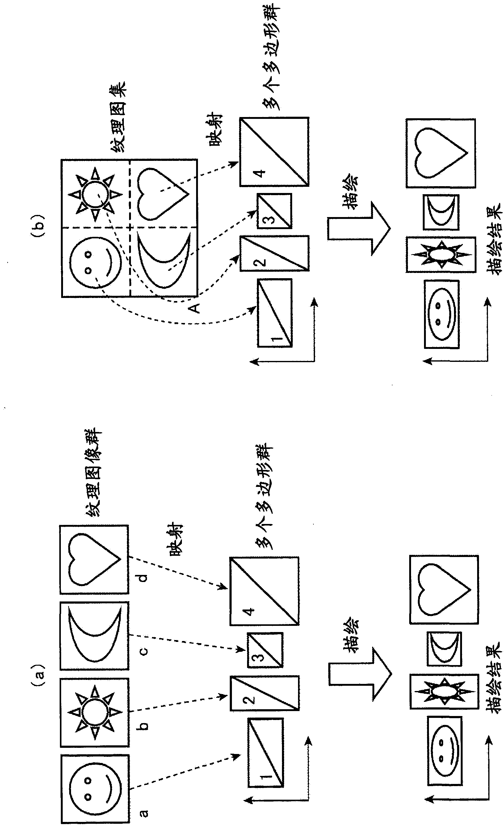
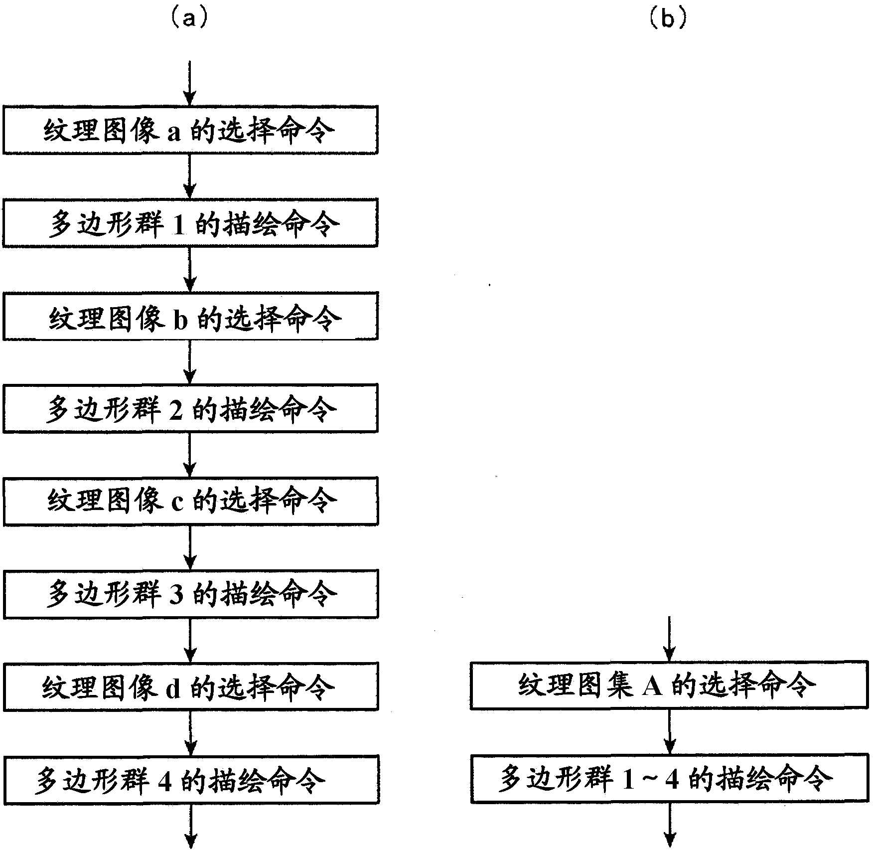
[0039] Figure 5 It is a configuration diagram showing the image rendering device according to the first embodiment.

[0040] Such as Figure 5As shown, the image rendering device includes a preprocessing unit 1 , an execution processing unit 2 , an HDD (hard disk device) 3 , and a polygon rendering device 4 . The preprocessing unit 1 constitutes a drawing data generation device, generates a tree structure, a polygon group, and a texture image cluster based on a tree structure, a polygon group, and a texture image group, and includes a node collection unit 11 and a texture atlas generation unit 12 . The execution processing unit 2 issues rendering commands to the polygon rendering device 4 based on the tree structure, polygon group, and texture map cluster generated by the preprocessing unit 1 , and includes a rendering node determination unit 21 , a rendering list generation unit 22 , and a rendering unit 23 . The HDD 3 is a storage device for storing the generation result ...


PUM


Abstract

A node gathering unit (11) has a polygon group and a texture image group as inputs, and determines nodes corresponding to a texture image group to bind. Said polygon group has a relationship represented by multiple detail levels in a tree structure, and expresses a model by means of the multiple detail levels. Each member of said texture image group is allocated uniquely to the polygon group. A texture atlas generation unit (12): uses node information generated by the node gathering unit (11) to bind the texture image group and generate a texture atlas group; and transforms texture coordinates of the vertices of the polygon group, said texture coordinates being transformed in correspondence to drawing positions.

Description

technical field [0001] The present invention relates to a rendering data generating device and an image rendering device that represent a two-dimensional or three-dimensional shape using a polygon group that represents a model at a plurality of levels of detail and is managed in a tree structure. Background technique [0002] In computer graphics, polygonal models are widely used as a means of expressing two-dimensional or three-dimensional shapes. The polygon model mainly regards the triangle as the unit shape, and uses its combination to express the shape. [0003] In order to improve the expressiveness of polygonal models, texture mapping that maps and draws a two-dimensional texture image onto a polygonal surface is widely used. Usually, in the rendering flow when texture mapping is used, a polygon rendering command is issued after a command to select a texture image to be used is issued to a polygon rendering device such as a GPU. Regarding the above selection command...

Claims


Application Information

Patent Timeline
Patent Type & Authority Applications(China)
IPC IPC(8): G06T15/04
CPCG06T15/04G06T11/001G06T11/203G06T17/20
Inventor 樱井智史窪山正一朗
Owner MITSUBISHI ELECTRIC CORP
Why Eureka
Try Eureka