Handle with safe locking device and circuit breaker comprising the handle

A safety lock and handle technology, used in emergency protection devices, circuits, and protection switch parts, etc., can solve the problems of inconsistent operating states of circuit breakers, inability to meet customer safety performance, and safety hazards.

Active Publication Date: 2014-09-24
EATON INTELLIGENT POWER LTD
View PDF4 Cites 5 Cited by
  • Summary
  • Abstract
  • Description
  • Claims
  • Application Information

AI Technical Summary

Problems solved by technology

[0003] Existing handles, due to the fixed connection between the handle base and the connecting mechanism of the handle, relative movement cannot occur
The handle with this structure can often only realize the locking of the circuit breaker in the opening position (OFF), but cannot identify the operating state of the circuit breaker. Under such circumstances, the handle in the prior art can also be locked in the opening position (OFF), but the circuit breaker is still in the on state, causing the handle indication to be inconsistent with the actual operating state of the circuit breaker, thus bringing about major safety hazards. Hidden danger
[0004] As people gradually pay more attention to the safety performance of the device, such traditional handles can no longer meet the customer's demand for higher safety performance.

Method used


Image

  • Handle with safe locking device and circuit breaker comprising the handle
  • Handle with safe locking device and circuit breaker comprising the handle
  • Handle with safe locking device and circuit breaker comprising the handle

Examples


Embodiment Construction

[0025] Embodiments of the disclosed apparatus are now described with reference to the following detailed description and accompanying drawings. Although the drawings are provided to illustrate some embodiments of the invention, the drawings are not necessarily to scale of a particular embodiment and certain features may be exaggerated, removed, or sectioned to better illustrate the invention.

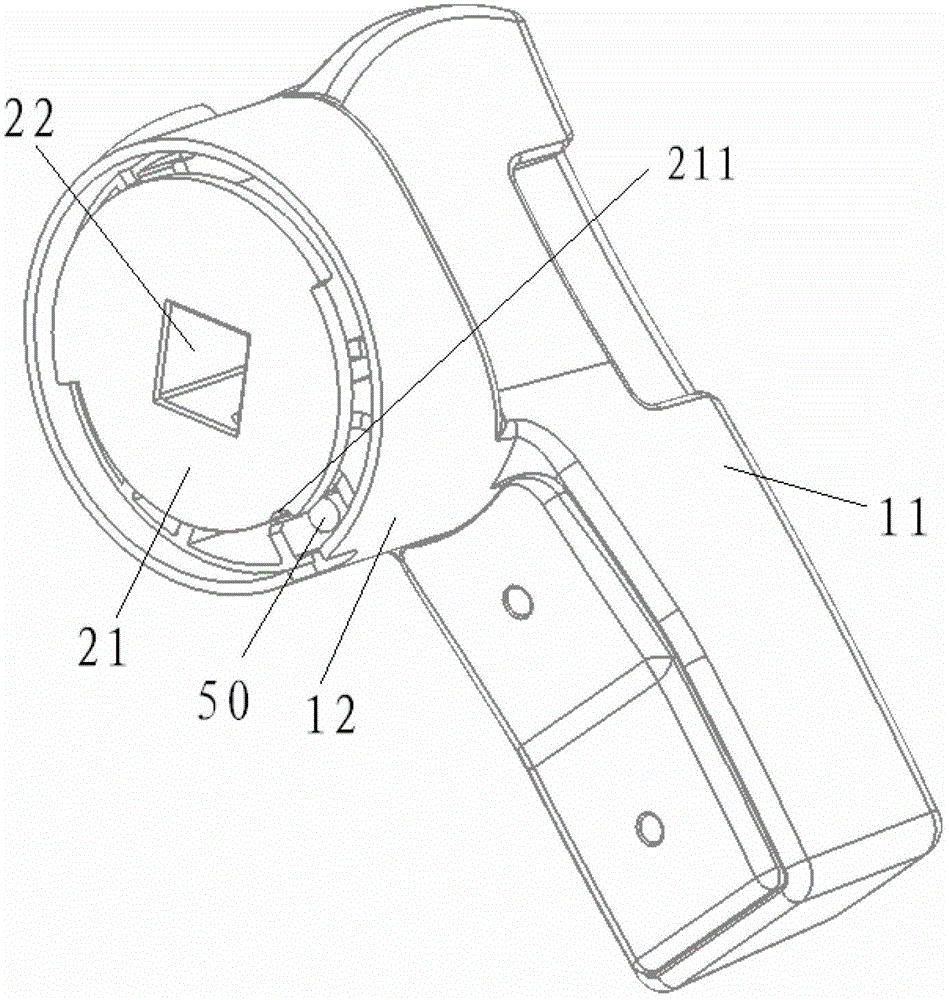
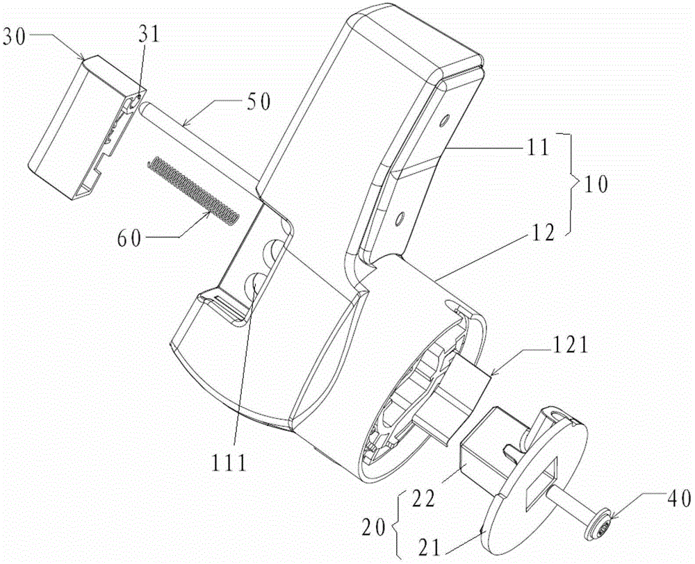
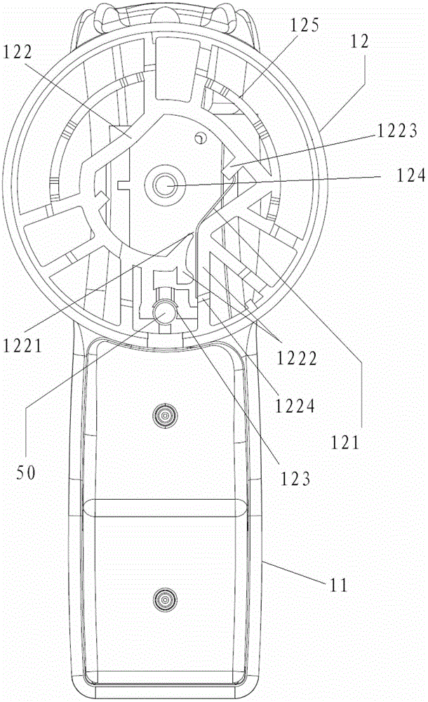
[0026] Such as figure 1 and figure 2 As shown, this embodiment provides a handle with a safety locking device, which is used to drive the moving contact of the switch device to rotate between the electrically connected closing position and the disconnected opening position relative to the static contact. The static contact is fixed in the housing of the switch device, the handle includes a handle base 10, one end is fixedly connected with the moving contact and the other end is connected with the handle base 10 to transmit torque, and a connection mechanism 20 for torque transmission ...


PUM


Abstract

A handle having a safe locking device, and a breaker comprising the handle, the handle drives the moving contact of a switching device to rotate between ON and OFF positions relative to a static contact, the static contact being fixed in the casing of the switching device; the handle comprises a handle base (10), a connection mechanism (20) with one end being fixedly connected to the moving contact, and the other end being connected to the handle base (10) to transfer torque, and a locking mechanism locking the handle base (10) and the connection mechanism (20) in the ON or OFF position under the normal operating state of the switching device; the connection mechanism (20) is connected to the handle base in the above mode, so that under an abnormal operating state where the moving contact is hard to separate from the static contact and based on the increase in separation resistance, the rotation of the handle base (10) drives the connection mechanism (20) to rotate relative to the handle base (10). As a result, when the handle base (10) is rotated to the OFF position, the connection mechanism (20) is located in an offset position offset from the OFF position, and thus the handle base (10) cannot be locked in the OFF position relative to the connection mechanism (20).

Description

technical field [0001] The invention relates to the technical field of switches, in particular to a handle with a safety locking device and a circuit breaker including the handle. Background technique [0002] In order to facilitate operation and assembly, and improve its safety performance, the low-voltage switchgear, especially the low-voltage circuit breaker, often needs to be controlled by a handle. [0003] The existing handle cannot move relative to each other because of the fixed connection between the handle base of the handle and the connecting mechanism. The handle with this structure can often only realize the locking of the circuit breaker in the opening position (OFF), but cannot identify the operating state of the circuit breaker. Under such circumstances, the handle in the prior art can also be locked in the opening position (OFF), but the circuit breaker is still in the on state, causing the handle indication to be inconsistent with the actual operating stat...

Claims


Application Information

Patent Timeline
Patent Type & Authority Applications(China)
IPC IPC(8): H01H9/28
CPCH01H9/28H01H71/521
Inventor 丁金华武军亮周辉
Owner EATON INTELLIGENT POWER LTD
Why Eureka
Try Eureka