
Electromagnetic device and application thereof

A technology of electromagnetic devices and solenoid valves, applied in the direction of electromechanical devices, valve devices, valve operation/release devices, etc., can solve the problems of large volume, copper consumption, small stroke, etc.

Inactive Publication Date: 2011-05-25
卢小平
View PDF7 Cites 1 Cited by
  • Summary
  • Abstract
  • Description
  • Claims
  • Application Information

AI Technical Summary

Problems solved by technology

Because the size of the air gap has a great influence on the electromagnetic force, the travel of traditional electromagnetic devices is relatively small
[0003] Since the force of the electromagnetic device is proportional to the number of ampere turns, unlike the motor, the force can be increased through the reducer, so the current is usually larger and the number of coil turns is also more, which means that the copper material is consumed and the volume is larger. Big

Method used


Image

  • Electromagnetic device and application thereof
  • Electromagnetic device and application thereof

Examples


Embodiment Construction

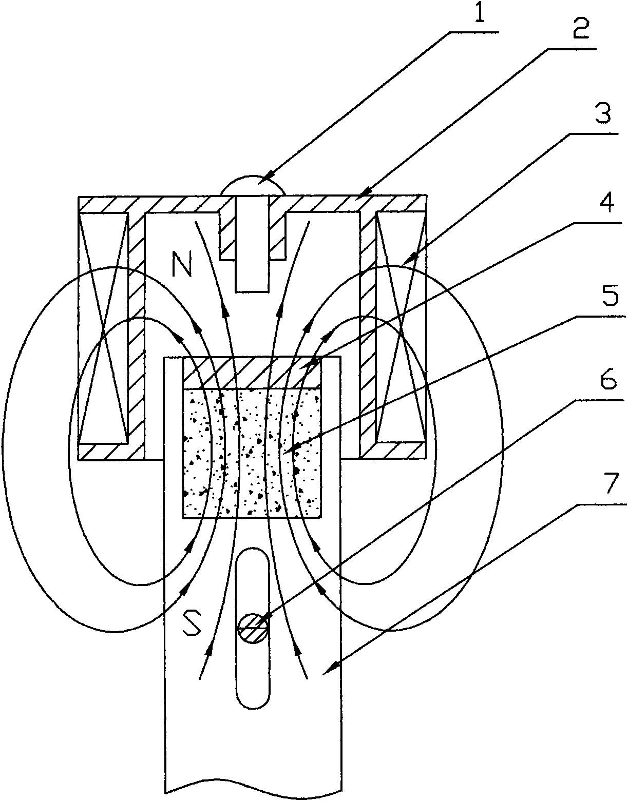
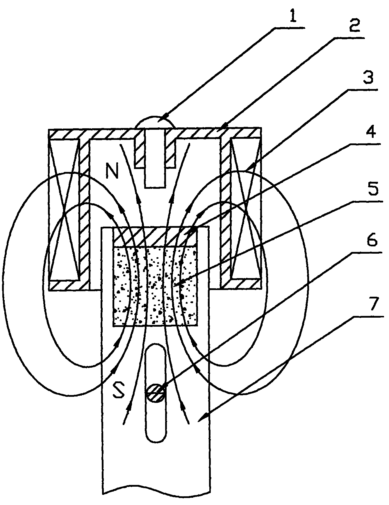
[0020] See figure 1 The electromagnetic device provided by the present invention is characterized in that it includes a bracket 2, a coil 3, a push-pull rod 7, and a permanent magnet 5. The coil 3 is wound on the bracket 2 with a hollow interior. The permanent magnet 5 is fixedly arranged in the push-pull rod 7, and the push-pull rod 7 can move in and out linearly in the hollow part of the coil under the interaction of magnetic force.

[0021] The front end surface of the bracket 2 is also provided with an upper end soft magnet 1 protruding inward for attracting and positioning the push-pull rod 7 at the upper end.

[0022] The rear section of the push-pull rod 7 is provided with a chute; the bracket 2 or the external support part is also fixedly provided with a lower end soft magnet 6 for attracting and positioning the push-pull rod 7 at the lower end.

[0023] The permanent magnet 5 is fixedly arranged in the front section of the push-pull rod 7 by a cover 4.

[0024] When the coil...


PUM


Abstract

The invention provides an electromagnetic device. The electromagnetic device is characterized by comprising a bracket, a coil, a push-pull rod and permanent magnets, wherein the coil is wound on the bracket, and the interior of the coil is hollow; the permanent magnets are fixedly arranged in the push-pull rod; the push-pull rod can linearly access and move in the hollow part of the coil under the interaction of magnetic forces; when the coil is excited, the push-pull rod can move upwards and is attracted on the top under the action of a soft magnet when reaching the upper end, and the coil can also be automatically held without current; and when the coil is reversely excited, the push-pull rod overcomes the attractive force of the soft magnet and moves downwards, the push-pull rod is pulled down from the soft magnet till the push-pull rod is blocked by the soft magnet, and then the push-pull rod is mutually attracted with the soft magnet. According to the electromagnetic device provided by the invention, the soft magnet for closing a magnetic circuit on the traditional electromagnetic device is changed, forces of different directions are generated among the permanent magnets when the coil is charged with the current of different directions, and then bidirectional motion is realized in the absence of the action of spring restoring force.

Description

Technical field [0001] The invention relates to automatic control technology, in particular to an electromagnetic device using permanent magnets and its application in manufacturing electromagnetic valves. Background technique [0002] Most of the traditional electromagnetic devices use soft magnets as the magnetic material, so that the electromagnetic device can have no residual magnetism when it is not excited, and the valve plate can be reset smoothly; the electromagnetic device forms a closed circuit when it is closed, which reduces the magnetic resistance and can greatly Reduce the self-holding excitation current, but in spite of this, there is still a current to maintain. Since the size of the air gap has a great influence on the electromagnetic force, the stroke of the traditional electromagnetic device is relatively small. [0003] Since it is not like a motor that can increase the power through a reducer, the force of the electromagnetic device is proportional to the numb...

Claims


Application Information

Patent Timeline
Patent Type & Authority Applications(China)
IPC IPC(8): H02K33/18F16K31/06
Inventor 卢小平
Owner 卢小平
Learn More