False cable joint

A cable dummy and cable technology, applied in the field of cable laying and installation, can solve the problems of inability to realize and the number of cable joints cannot be arbitrarily reduced, and achieve the effect of reducing the influence of induced voltage

Inactive Publication Date: 2014-09-24
李超 +2
View PDF2 Cites 5 Cited by
  • Summary
  • Abstract
  • Description
  • Claims
  • Application Information

AI Technical Summary

Problems solved by technology

The design regulations have strict regulations on the limit value of the induced voltage of the metal sheath, so the number of cable joints cannot be reduced arbitrarily
To be able to ensure that the induced voltage of the cable sheath does not exceed the specified value, and reduce the number of real connectors, the existing technology has not been able to achieve

Method used


Image

  • False cable joint
  • False cable joint
  • False cable joint

Examples


Embodiment 1

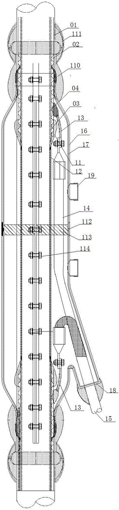
[0077] Such as figure 1 As shown, the present invention adopts the method of stripping from the outer insulating layer of the cable to the semiconductive buffer zone to make a false joint. The manufacturing method of this cable dummy joint comprises the following steps,

[0078] 1.1) Strip the part where the cable needs to be equipped with joints, and break the outer insulating layer 01, shielding sheath 02 and semi-conductive buffer strip 03; the breaking length of the outer insulating layer 01 is greater than the breaking length of the shielding sheath 02; each cable The breaking length of the layer structure depends on the voltage level. The breaking length of the outer insulating layer 01 is about 1750-2000mm, the breaking length of the shielding sheath 02 is about 1100-1750mm, and the breaking length of the semiconducting buffer belt 03 is about 700-1600mm;

[0079] 1.2) Close the breakage of the shielding sheath 02: use the semi-conductive tape 11 to wrap half-fold from...

Embodiment 2

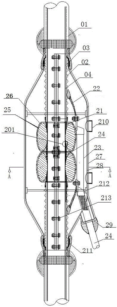
[0087] figure 2 The manufacturing method of the cable dummy joint shown includes the following steps:

[0088] 2.1) Strip the part where the cable needs to be equipped with joints, and break the outer insulating layer 01, shielding sheath 02, semi-conductive buffer strip 03 and outer semi-conductive layer 04 in sequence; the breaking length of the outer insulating layer 01 is greater than the shielding sheath The breaking length of 02, the breaking length of the shielding sheath 02 is greater than the breaking length of the semiconducting buffer zone 03, the breaking length of the semiconducting buffer zone 03 is greater than the breaking length of the outer semiconducting layer 04; the broken length of each layer of the cable depends on different voltages The grade varies, usually the breaking length of the outer insulating layer 01 is 800-1200mm, the breaking length of the shielding sheath is 350-400mm, the breaking length of the semi-conductive buffer zone is 300-350mm, an...

Embodiment 3

[0100] image 3 The cable dummy joints shown can be used in cable laying construction with low voltage level, generally 110KV and below systems. Its preparation method comprises the following steps:

[0101] 3.1) Strip the part where the cable needs to be equipped with joints, and break the outer insulating layer, shielding sheath, semi-conductive buffer zone and outer semi-conductive layer in sequence; the breaking length of the outer insulating layer is greater than the breaking length of the shielding sheath, and the shielding The breaking length of the sheath 02 is greater than that of the semiconducting buffer zone, and the breaking length of the semiconducting buffer zone is greater than that of the outer semiconducting layer; the breaking length of each layer of the cable is adjusted according to the voltage level. The breaking length is 800-1200mm, the breaking length of the shielding sheath is 350-400mm, the breaking length of the semi-conductive buffer belt is 300-3...


PUM


Abstract

The invention discloses a false cable joint, applied to the laying process of a long cable to replace part of real joints to achieve cross interconnection. During the manufacture of the false cable joint provided by the invention, the cable at the position where a joint needs to be arranged is stripped in three modes, wherein the first mode is stripping from an outer insulating layer of the cable to a semiconductive buffer band and then recovering insulation and waterproofness of the cable; the second mode is stripping from an outer insulating layer of the cable to an outer semiconductive layer, wrapping the outer semiconductive layer by an annular stress cone or a semiconductive band and an insulating tape in layers to homogenize field intensity distribution and limit an electric field within a safe range, and then recovering insulation and waterproofness of the cable; the third mode is only stripping part of an outer insulating layer, earthing a shielding sheath and then recovering insulation and waterproofness of the cable. Cross interconnection is achieved by replacing the real joints with the false joints to reduce influence of induced voltage of the metal sheath of the long cable, and thereby required investment for joints in a cable laying project is reduced on basis of not changing a traditional design philosophy of cross interconnection .

Description

technical field [0001] The invention relates to the technical field of cable laying and installation, in particular to a cable dummy joint. Background technique [0002] At present, in the laying process of high-voltage or ultra-high-voltage XLPE insulated power cables, in order to reduce the influence of induced voltage on the metal sheath, cable true joints are generally used to realize cross-connection of long cables. As the requirements of local planning become more and more stringent, it is more and more popular to use cables for underground overhead lines, and then the application of high-voltage or ultra-high-voltage XLPE insulated power cables is becoming more and more extensive. Due to the complex structure of extra-high voltage cable accessories, it is difficult to calculate the accurate electric field distribution inside the accessories, and the requirements for on-site installation and laying and on-site environment are very high, so accidents in power cable syst...

Claims


Application Information

Patent Timeline
Patent Type & Authority Applications(China)
IPC IPC(8): H02G15/02H02G15/04
Inventor 李超徐艺李有胜刘小光索进章
Owner 李超
Why Eureka
Try Eureka