Fluid ejection device and medical apparatus

A technology of fluid jetting and fluid, applied in the direction of fluid jetting scalpel, medical science, surgery, etc.

Inactive Publication Date: 2014-10-01
SEIKO EPSON CORP
View PDF9 Cites 3 Cited by
  • Summary
  • Abstract
  • Description
  • Claims
  • Application Information

AI Technical Summary

Problems solved by technology

[0006] However, in surgeries using fluid ejection devices, there are cases where other medical devices that generate electrical noise, such as electrocutters, are used at the same time
If other medical equipment comes into contact with the jet tube of the fluid jet device, there is a possibility of electrical noise propagating through the jet tube to the piezoelectric element
[0007] In addition, this problem is not limited to fluid ejection devices that use piezoelectric elements to impart pulsation to the fluid, but is generally a common problem in fluid ejection devices that use actuators that operate when supplied with electric energy.

Method used


Image

  • Fluid ejection device and medical apparatus
  • Fluid ejection device and medical apparatus
  • Fluid ejection device and medical apparatus

Examples


no. 1 approach

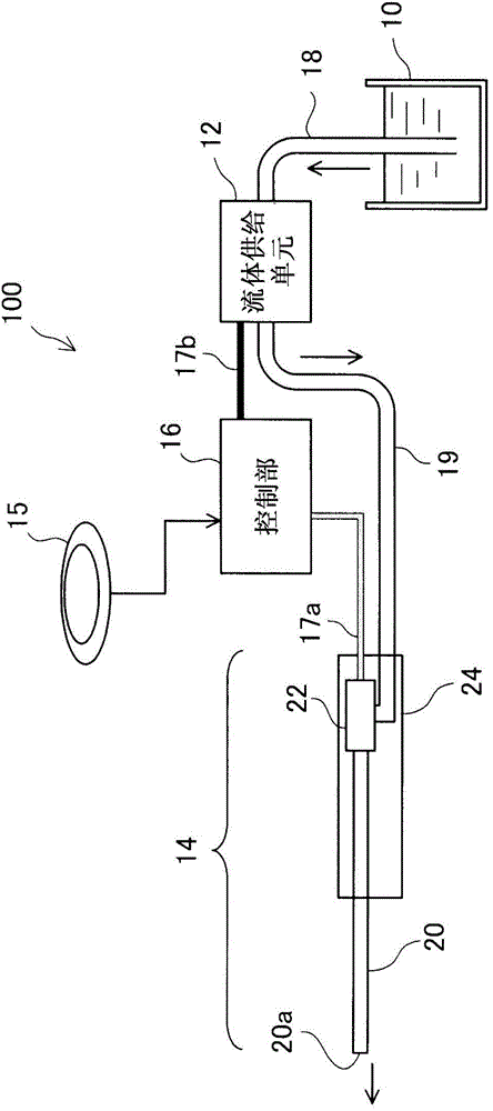
[0033] figure 1 It is an explanatory diagram showing the configuration of the fluid ejection device 100 as one embodiment of the present invention.

[0034] The fluid ejection device 100 of this embodiment is a medical device used in a medical institution, and has a function as a scalpel for incising or excision of an affected area by ejecting a fluid to the affected area.

[0035] The fluid ejection device 100 includes a fluid container 10 , a fluid supply unit 12 , a hand piece 14 , a foot switch 15 , and a control unit 16 . The fluid container 10 and the fluid supply unit 12 are connected through a connection pipe 18 , and the fluid supply unit 12 and the hand piece 14 are connected through a connection pipe 19 . In this embodiment, the connecting pipes 18 and 19 are formed of insulating resin.

[0036]The fluid container 10 contains physiological saline as a fluid supplied to the hand piece 14 . However, instead of physiological saline, the fluid container 10 may accomm...

no. 2 approach

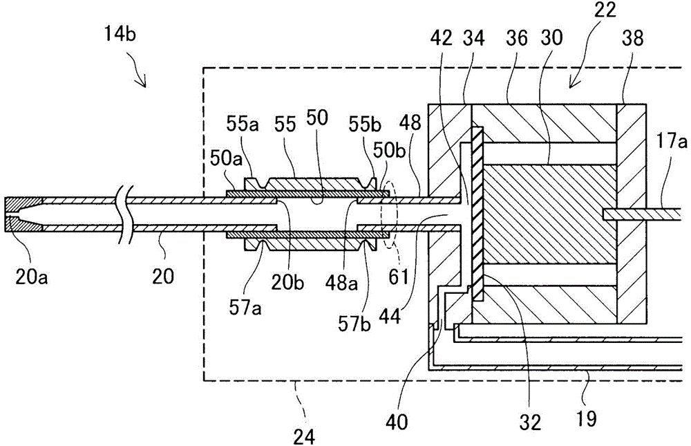
[0059] image 3 It is an enlarged cross-sectional view showing a part of the internal configuration of the hand tool 14b according to the second embodiment. and figure 2 The first embodiment shown is different only in that the reinforcing tube 55, the overlapping portion of the insulating tube 50, and the fluid ejection tube 20, and the overlapping portion of the reinforcing tube 55, the insulating tube 50, and the outlet tube 48 are crimped from the outer peripheral side. ) while fixing this point, the other configurations are the same as those of the first embodiment. In addition, in image 3 , the crimping marks, that is, the crimping portions 57a, 57b are drawn.

[0060] According to this second embodiment, in addition to achieving the same effects as those of the above-mentioned first embodiment, the reinforcement tube 55, the insulating tube 50, and the fluid ejection tube 20 can be firmly fixed by crimping, and can be firmly fixed. Reinforcing tube 55 , insulating ...

no. 3 approach

[0062] Figure 4 It is an enlarged cross-sectional view showing a part of the internal configuration of the hand tool 14c according to the third embodiment. and image 3 The second embodiment shown differs only in that the shape and size of the inner circumference of the portion in contact with the fluid among the inner circumference of the insulating tube 50 is substantially the same as the shape and size of the inner circumference of the fluid ejection tube 20, and the other configurations are the same as those of the fluid injection tube 20. The second embodiment is the same.

[0063] Specifically, in the present embodiment, the inner diameter of the portion of the inner periphery of the insulating tube 50 that is in contact with the fluid is reduced. In addition, the inner diameter of the insulating tube 50 at the portion in contact with the fluid is substantially equal to the inner diameter of the fluid ejection tube 20 . Therefore, there is no level difference in the ...


PUM


Abstract

A fluid ejection device which ejects a fluid includes: an ejection tube containing a conductive material and having an opening for the fluid; a fluid chamber communicating with the ejection tube; an actuator which operates on receiving supply of electric energy, thereby changing pressure of the fluid in the fluid chamber; and an insulating member which is made of an insulating material and electrically insulates a member forming the fluid chamber and the ejection tube from each other.

Description

technical field [0001] The present invention relates to a fluid ejection device and medical equipment using the fluid ejection device. Background technique [0002] A device described in Patent Document 1, for example, is known as a medical device that treats an affected part with a jetted fluid. In the fluid ejection device described in Patent Document 1, the volume of the fluid chamber is increased or decreased by driving the piezoelectric element, and a pulsating flow (pulse flow) is ejected from the ejection tube. [0003] prior art literature [0004] patent documents [0005] Patent Document 1: Japanese Patent Laid-Open No. 2008-82202 [0006] However, in an operation using a fluid ejection device, there are cases where other medical equipment (such as an electric cutter) that generates electrical noise is used at the same time. If other medical equipment comes into contact with the ejection tube of the fluid ejection device, there is a possibility that electrical ...

Claims


Application Information

Patent Timeline
Patent Type & Authority Applications(China)
IPC IPC(8): A61B17/32
CPCA61B17/3203A61B2560/02A61B2018/00083
Inventor 小岛英挥关野博一
Owner SEIKO EPSON CORP
Why Eureka
Try Eureka