Automatic waste discharge laser for position-sleeving cutting

An automatic row and laser machine technology, applied in the field of laser machines, can solve the problems of long mold adjustment time, expensive mold cycle, high consumption of auxiliary materials, etc., and achieve the effects of cost saving, resource consumption reduction, and high waste discharge yield rate.

Pending Publication Date: 2018-10-26
SHENZHEN BSC TECHNOLOGY CO LTD
View PDF0 Cites 2 Cited by
  • Summary
  • Abstract
  • Description
  • Claims
  • Application Information

AI Technical Summary

Problems solved by technology

The commonly used die-cutting production and processing equipment on the market can be roughly divided into the following categories: flat knife die-cutting machine, combined line die-cutting machine, circular knife die-cutting machine and laser cutting machine, among which flat knife die-cutting machine can only Produce single-cut products; the combined line die-cutting machine can produce multiple-cut products, but the existing problems are the long mold adjustment time and the consumption of auxiliary materials; the circular knife die-cutting machine can produce multiple punches Cutting products, the problem is that the mold is expensive and the cycle is long, and the accuracy of multiple punching products is low; the laser cutting machine does not need molds during production, the adjustment time is short, and the stored parameters can be directly called during secondary production, but there are The problem is that it cannot be produced automatically, it needs manual loading and unloading of products, and only sheet products can be produced, so the products produced cannot use automatic placement

Method used


Image

  • Automatic waste discharge laser for position-sleeving cutting
  • Automatic waste discharge laser for position-sleeving cutting
  • Automatic waste discharge laser for position-sleeving cutting

Examples


Embodiment Construction

[0015] In order to make the object, technical solution and advantages of the present invention clearer, the present invention will be further described in detail below in conjunction with the accompanying drawings and embodiments. It should be understood that the specific embodiments described here are only used to explain the present invention, not to limit the present invention.

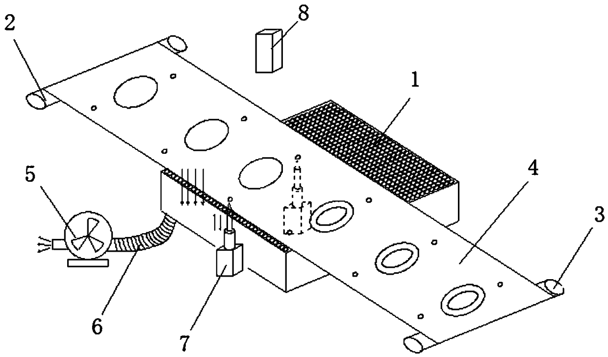
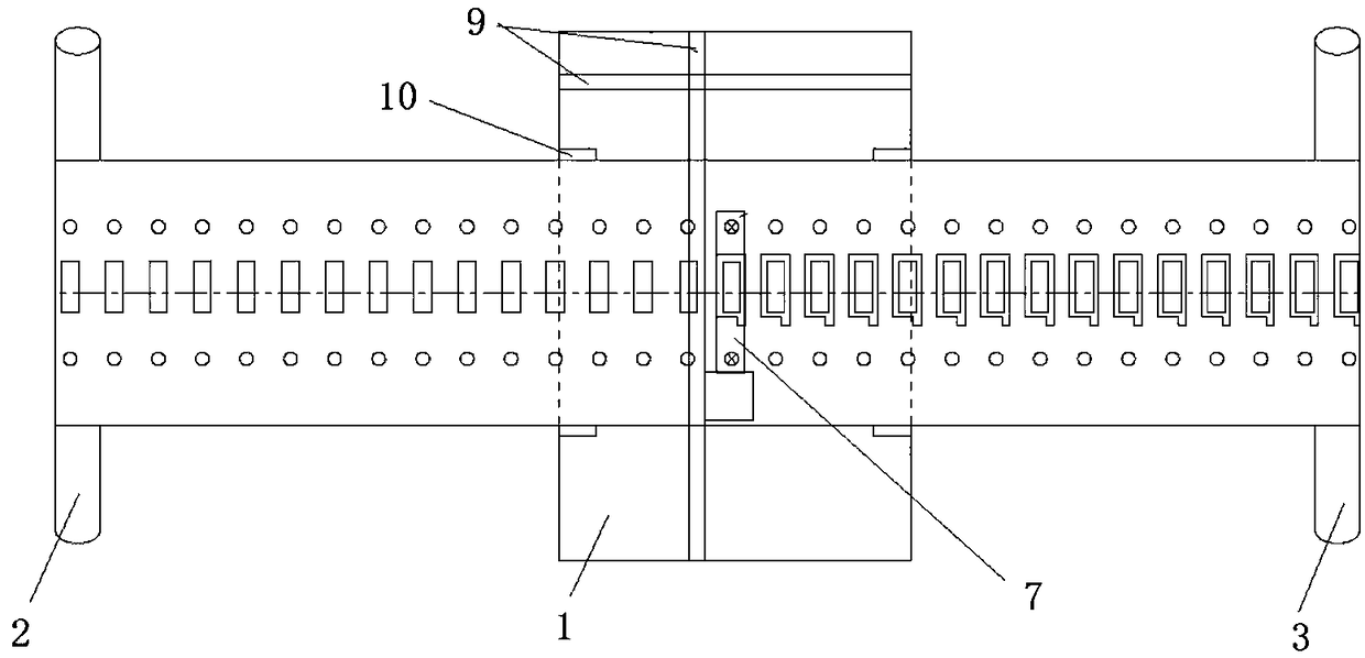
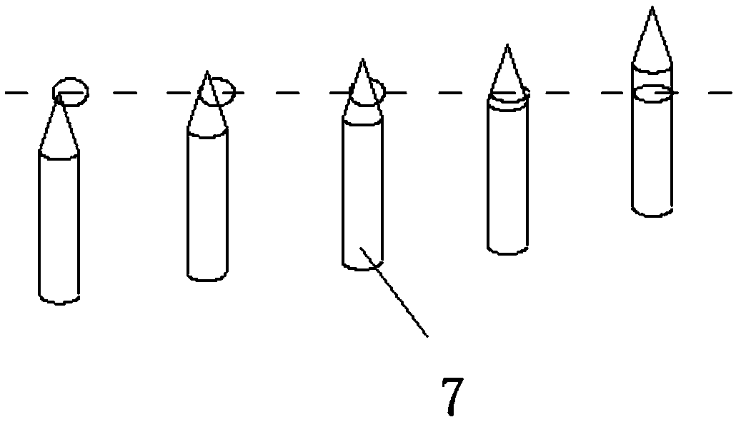
[0016] Such as Figure 1-Figure 3 As shown, a laser machine for automatic waste discharge for sleeve cutting includes a workbench 1, the workbench 1 is a honeycomb panel sealed below, and the left and right sides of the workbench 1 are respectively provided with a discharge shaft 2 and a material receiving shaft. Shaft 3, a material strip 4 is arranged between the discharging shaft 2 and the receiving shaft 3, several positioning holes are evenly distributed on both sides of the material strip 4, and an air suction pump 5 is arranged below the workbench 1, so that The air suction pump 5 is connect...


PUM


Abstract

The invention relates to the technical field of lasers, in particular to an automatic waste discharge laser for position-sleeving cutting. The automatic waste discharge laser for position-sleeving cutting comprises a worktable, wherein the worktable is a cellular board sealed below, an emptying shaft and a material receiving shaft are separately arranged on the left and right sides of the worktable, a strip is arranged between the emptying shaft and the material receiving shaft, a plurality of positioning holes are uniformly formed in two sides of the strip, a suction pump is arranged below the worktable, the suction pump is connected to the bottom of the worktable through an inhaling hose, positioning devices are separately arranged below the positioning holes in two sides of the strip, the positioning devices are air cylinders, positioning pins are arranged on the air cylinders, a laser head is arranged above the strip, X-axis and Y-axis coordinate systems are arranged below the worktable, the laser head is connected to the X-axis and Y-axis coordinate systems, and two adjustable limiting blocks are separately arranged at the left and right ends of the worktable.

Description

technical field [0001] The invention relates to the technical field of laser machines, in particular to a laser machine for nesting and cutting automatic waste discharge. Background technique [0002] With the development of science and technology, electronic products continue to develop in the direction of miniaturization, light weight and precision. Die-cut parts are widely used in electronic products, and the competition in the production and processing industry of die-cut parts is also becoming increasingly fierce. The commonly used die-cutting production and processing equipment on the market can be roughly divided into the following categories: flat knife die-cutting machine, combined line die-cutting machine, circular knife die-cutting machine and laser cutting machine, among which flat knife die-cutting machine can only Produce single-cut products; the combined line die-cutting machine can produce multiple-cut products, but the existing problems are the long mold adj...

Claims


Application Information

Patent Timeline
IPC IPC(8): B23K26/38B23K26/70B23K37/04
CPCB23K26/38B23K26/702B23K37/04
Inventor 罗永锋
Owner SHENZHEN BSC TECHNOLOGY CO LTD
Why Eureka
Try Eureka