Method for sending signal by smart antenna and smart antenna thereof

A technology for smart antennas and signal transmission, applied in diversity/multi-antenna systems, independent non-interactive antenna combinations, space transmit diversity, etc., can solve problems such as large antenna arrays, difficult engineering implementation, and large wind resistance of smart antennas

Inactive Publication Date: 2009-08-05
CHINA MOBILE COMM GRP CO LTD
View PDF0 Cites 3 Cited by
  • Summary
  • Abstract
  • Description
  • Claims
  • Application Information

AI Technical Summary

Problems solved by technology

[0007] However, the antenna array of the existing smart antenna system is relatively large, so the wind resistance borne by the smart antenna is relatively large, which makes the engineering realization more difficult, and the antenna needs to be remodeled on a large scale during the system evolution

Method used


Image

  • Method for sending signal by smart antenna and smart antenna thereof
  • Method for sending signal by smart antenna and smart antenna thereof
  • Method for sending signal by smart antenna and smart antenna thereof

Examples


Embodiment 1

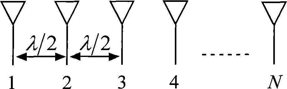
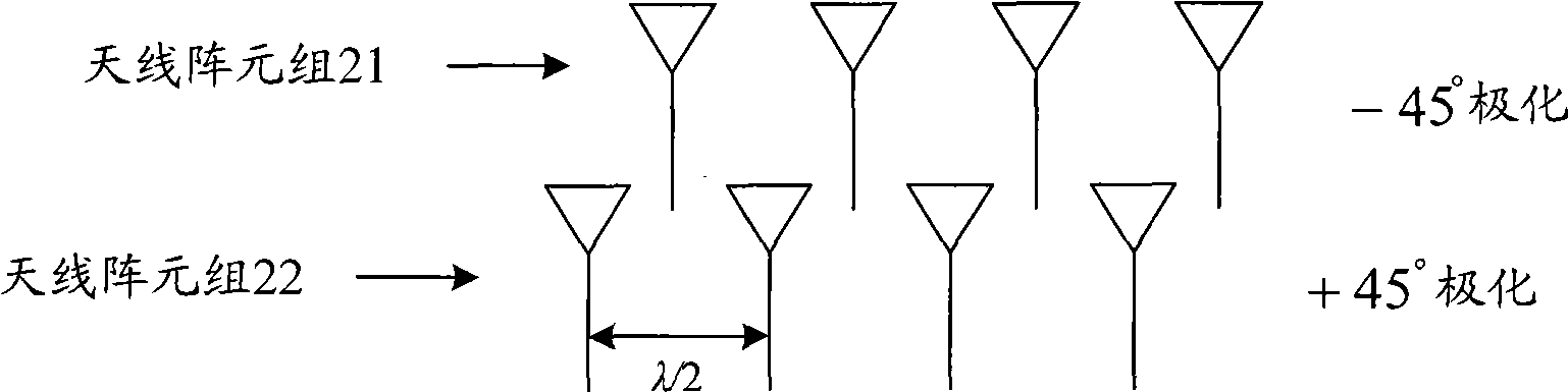
[0024] This embodiment transforms the existing smart antenna, that is, keeps the number of antenna array elements constant, and divides the antenna array elements into two groups, each group includes at least 2 antenna array elements, and the antenna array elements in each group The distance between the elements is less than or equal to λ / 2 to reduce the size of the smart antenna array. The antenna elements in each group adopt the same polarization mode, so that the antenna elements in the group can be used as a smart antenna array for beamforming together. , through the beamforming of the smart antenna array, the transmitted signal can effectively meet the requirements of system coverage. The two groups of antenna array elements adopt different polarization modes, such as mutually orthogonal polarization modes. The spatial fading characteristics of two sets of antenna elements that are orthogonal to each other are independent or less correlated, which can meet the correlation...

Embodiment 2

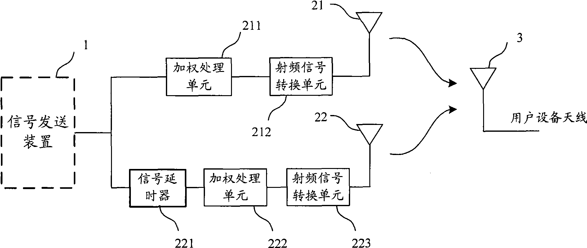
[0035] This embodiment transforms the existing smart antenna, that is, keeps the number of antenna array elements constant, and divides the antenna array elements into two groups, each group includes at least 2 antenna array elements, and the antenna array elements in each group The distance between the elements is less than or equal to λ / 2 to reduce the size of the smart antenna array. The antenna elements in each group adopt the same polarization mode, so that the antenna elements in the group can be used as a smart antenna array for beamforming together. , through the beamforming of the smart antenna array, the transmitted signal can effectively meet the requirements of system coverage. The two groups of antenna elements adopt the same polarization mode, such as vertical polarization mode. In this embodiment, a signal delayer is connected in series at one end of one group of antenna elements, so that there is a certain time delay when one group of antenna elements transmits...


PUM


Abstract

The invention discloses a method for sending signals by an intelligent antenna and the intelligent antenna, which aim at achieving the purpose of realizing miniaturization of the intelligent antenna and simultaneously guaranteeing the signal transmission performance. The intelligent antenna comprises a first antenna array element group and a second antenna array element group; the second antenna array element group is connected with a signal delayer which is used for delaying set time of signals to be sent; and the second antenna array element group is used for sending signals to be sent after the delay processing of the signal delayer so as to lead the second antenna array element group to have a certain time delay corresponding to the first antenna array element when sending signals. The invention utilizes time delay emission diversity to obtain multi-path combined gain, thus realizing miniaturization of the intelligent antenna and simultaneously guaranteeing the signal transmission performance.

Description

technical field [0001] The invention relates to the smart antenna technology in the field of mobile communication, in particular to a method for sending signals by the smart antenna and the smart antenna. Background technique [0002] The current multi-antenna technology mainly includes a smart antenna technology and a Multiple-Input Multiple-Output (Multiple-Input Multiple-Output, MIMO for short) technology. [0003] MIMO technology uses multiple antennas to suppress channel fading or increase system capacity, which can provide multiplexing gain and space diversity gain for the system. Among them, space multiplexing technology can greatly improve channel capacity, and space diversity can improve channel reliability and reduce channel error. code rate. MIMO technology can effectively improve system performance and spectrum utilization. The MIMO technology mainly uses the independence of the fading characteristics of the space channel on different antenna pairs to obtain di...

Claims


Application Information

Patent Timeline
Patent Type & Authority Applications(China)
IPC IPC(8): H04B7/04H04B7/06H01Q21/28
Inventor 徐晓东刘光毅王启星崔春风黄宇红
Owner CHINA MOBILE COMM GRP CO LTD
Why Eureka
Try Eureka