Engine cooling apparatus and engine cooling method

A cooling device and engine technology, applied in the direction of engine cooling, cooling device control device, engine components, etc., can solve the problems of increased fuel consumption, and achieve the effects of reducing effective utilization, avoiding large-scale, and cost reduction

Inactive Publication Date: 2014-08-13
CALSONIC KANSEI CORP +1
View PDF11 Cites 3 Cited by
  • Summary
  • Abstract
  • Description
  • Claims
  • Application Information

AI Technical Summary

Problems solved by technology

[0003] In the above-mentioned diesel engine, if the high-temperature automobile exhaust gas is returned to the intake air of the engine as it is, soot (SOOT) will be generated and the fuel consumption will increase

Method used


Image

  • Engine cooling apparatus and engine cooling method
  • Engine cooling apparatus and engine cooling method
  • Engine cooling apparatus and engine cooling method

Examples


Embodiment Construction

[0041] Embodiments of the present invention will be described below based on the drawings.

[0042] In the present embodiment, the engine cooling device 2 and the method of cooling the engine are applied to a vehicle equipped with an engine 4 (here, a diesel engine) that responds to trucks or automobile exhaust gas restrictions with a large-capacity EGR system or the like. .

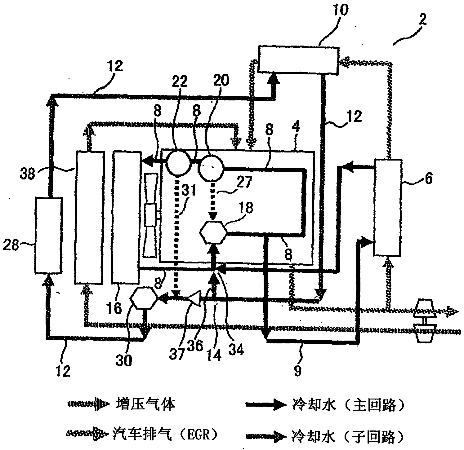
[0043] figure 1 It is a block diagram showing the configuration of the engine cooling device 2 according to the first embodiment.

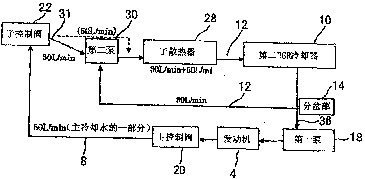
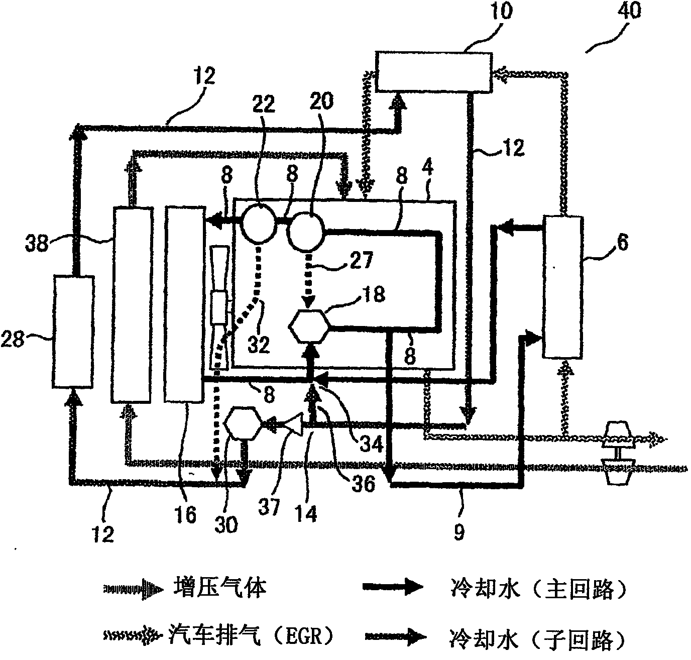
[0044] The cooling device 2 of the engine has the following two circuits: the main circuit 8 of cooling water, which uses the main radiator 16 to cool the engine 4 and the first EGR cooler 6; The low-temperature cooling water cools the second EGR cooler 10 .

[0045] In addition, a branch portion 14 is provided on the above-mentioned sub-circuit 12. According to predetermined conditions, the cooling water circulating in the sub-circuit 12 flows into the main circuit 8 from...


PUM


Abstract

The present invention relates to an engine cooling apparatus which comprises an EGR system or the like, and an engine cooling method. Provided are the engine cooling apparatus and the engine cooling method which are capable of reducing the capacity of a main radiator, saving costs, and effectively using a mounting space by providing a sub-radiator having an auxiliary function for the main radiator. A sub-control valve (22) is disposed to split and send a portion of a coolant sent to a main radiator (16) to a sub-circuit when a temperature of the coolant is higher than an upper limit of the temperature of the coolant in a normal engine state, as the result of detecting the temperature of the coolant in a main circuit. The coolant sent by the sub-control valve (22) to the sub-circuit (12) is cooled by a sub-radiator (28) and introduced into a cooler device, and the coolant at the sub-circuit (12) is split to be returned to an upper stream portion of a first pump (18) of the main circuit (8).

Description

technical field [0001] The present invention relates to an engine cooling device having an EGR system and the like, and a cooling method thereof. Background technique [0002] Conventionally, as a countermeasure against air pollution caused by automobile exhaust, an EGR system (automobile exhaust gas recirculation system) that recirculates automobile exhaust to the engine has been widely used in vehicles equipped with diesel engines. [0003] In the above-mentioned diesel engine, if the high-temperature automobile exhaust gas is recirculated to the intake air of the engine as it is, soot (SOOT) will be generated, and the fuel consumption will increase. As a means of solving these problems, an EGR cooler (heat exchanger) is generally installed to cool the exhaust gas of the vehicle with cooling water and return it to the engine. Most of the cooling water used in the above-mentioned EGR cooler also serves as cooling water for cooling the engine. [0004] In the main cooling ...

Claims


Application Information

Patent Timeline
Patent Type & Authority Applications(China)
IPC IPC(8): F01P3/18F01P3/20F01P5/12F01P7/16F02M25/07
CPCF01P3/20F01P2060/00F01P3/12F02M25/0738F01P2005/105F01P2037/02F01P2060/02F01P2060/18F02M25/0732F01P7/165F01P2060/16F01P2007/146F02M26/33
Inventor 金田崇稻叶纯平
Owner CALSONIC KANSEI CORP
Why Eureka
Try Eureka