A scalable ultrasonic welding tool base and ultrasonic welding tool

An ultrasonic welding and tooling technology, which is applied in welding equipment, manufacturing tools, non-electric welding equipment, etc., can solve problems such as damage to welding heads and ultrasonic machines, poor product quality stability, and repeated debugging of machines, so as to reduce adjustment time and reduce The effect of production quantity, improvement of stability and welding efficiency

Active Publication Date: 2016-04-20
ZHEJIANG WEITAI AUTOMOBILE PARTS
View PDF4 Cites 1 Cited by
  • Summary
  • Abstract
  • Description
  • Claims
  • Application Information

AI Technical Summary

Problems solved by technology

The main disadvantages of the traditional structure tooling are: the tooling corresponds to the product structure one by one, and the product models continue to increase, so a large number of welding heads and bases need to be produced; frequent replacement of welding heads is likely to cause damage to the welding head and the ultrasonic machine, which greatly reduces Its service life; the welding head is frequently replaced, the machine needs to be debugged repeatedly, the stability of product quality is relatively poor, and it affects production efficiency

Method used


Image

  • A scalable ultrasonic welding tool base and ultrasonic welding tool
  • A scalable ultrasonic welding tool base and ultrasonic welding tool
  • A scalable ultrasonic welding tool base and ultrasonic welding tool

Examples


Embodiment 1

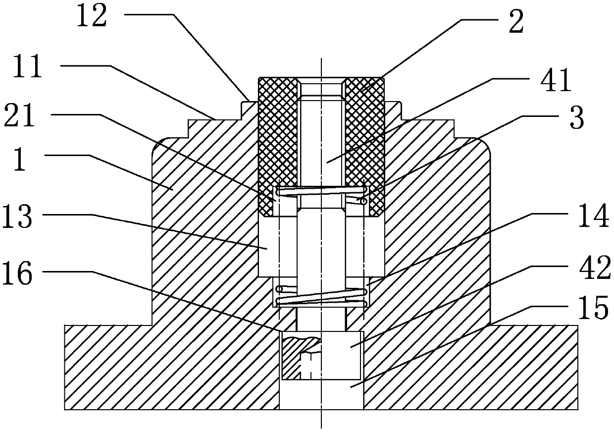
[0019] Such as figure 2 As shown, a telescopic ultrasonic welding tooling base includes a base body 1, the side of the base body has a stepped surface I11, the top of the base body 1 has a placement surface 12, and the base body 1 has a hollow cavity 13, the hollow cavity 13 The top is open, and the placement surface 12 is arranged around the top opening of the hollow cavity 13 to form a circle. The hollow cavity 13 is covered with a central shaft 2, and the hollow cavity 13 has a spring 3 inside. The bottom wall of the hollow cavity 13 has a concave groove I14 , the bottom end of the spring 3 extends into the groove I14 and is supported on the bottom end face of the groove I14, the bottom end of the spring 3 is radially limited in the groove I14, and the top end of the spring 3 is against the center axis 2 The bottom, preferably the bottom of the central axis 2 has a groove II 21, the top of the spring 3 is in the groove II 21, the top of the spring 3 is radially limited in ...

Embodiment 2

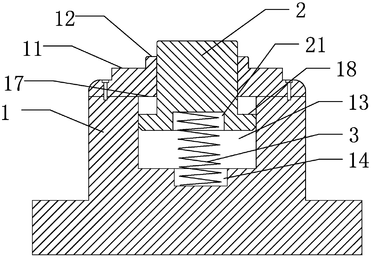
[0023] Such as image 3 As shown, the structure is basically the same as that of Embodiment 1, the difference is that no bolts are set in this structure, but a stepped surface III17 is set on the inner wall surface of the hollow cavity 13, wherein, preferably, the base body 1 is composed of upper and lower parts, and the steps The surface III17 is formed by the junction of the upper and lower parts, which is convenient for manufacturing the cross-sectional area of ​​the hollow cavity part below the stepped surface III17 is larger than the cross-sectional area of ​​the hollow cavity part above the stepped surface III17. A stepped surface IV18 is set on the outer wall of the central axis 2, and the step The cross-sectional area of ​​the central axis part below the surface IV18 is larger than the cross-sectional area of ​​the central axis part above the stepped surface III17, and the central axis 2 is limited in the hollow cavity 13 of the base body 1 by the structure of the stepp...

Embodiment 3

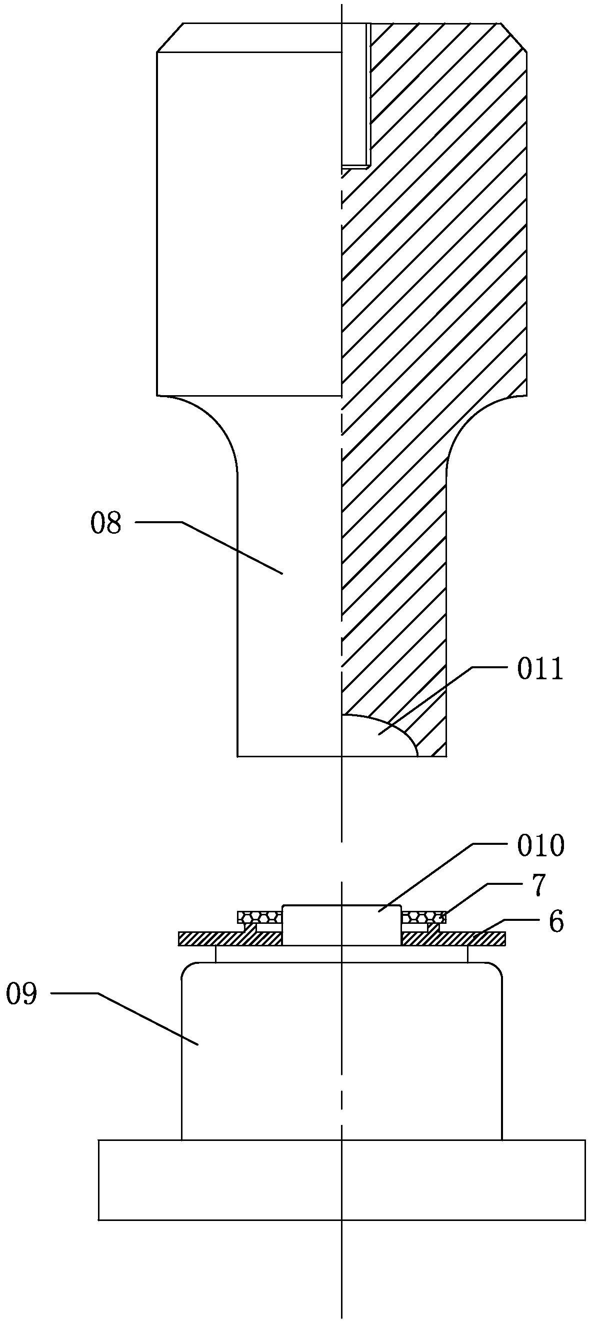
[0025] Such as Figure 4 As shown, the ultrasonic welding tooling includes a base and a welding head 5. The base adopts the scalable ultrasonic welding tooling base described in Embodiment 1. The bottom surface of the welding head 5 is a plane, and the welding head 5 is installed on a lifting mechanism for scalable ultrasonic welding. The base of the tooling is located under the welding head 5. When welding starts, the welding head 5 descends and presses down on the central axis 2, and the spring gradually shortens downward until the flat part of the welding head touches the seal 7 and gradually moves downward to weld the seal on On the filter end cover 6. Compared with the ultrasonic welding tool with traditional structure, the welding head is changed from a concave structure to a flat structure, and the base is changed from a three-step integral structure to a two-step split structure. The central axis, when the ultrasonic machine is welding, the central axis 2 can be stret...


PUM


Abstract

The invention provides a telescopic ultrasonic welding fixture base and an ultrasonic welding fixture. The telescopic ultrasonic welding fixture base comprises a base main body, wherein a placing surface is arranged at the top of the base main body, a hollow cavity is formed in the base main body, an opening is formed in the top of the hollow cavity, the placing surface surrounds the opening in the top of the hollow cavity, a center shaft is sleeved in the hollow cavity, a spring used for ejecting the center shaft to the outside of the opening in the top of the hollow cavity is arranged in the hollow cavity, and a support part which supports the spring is arranged in the hollow cavity. Meanwhile, the invention provides the ultrasonic welding fixture. The base disclosed by the invention is manufactured to be a telescopic structure relying on the spring, when a product model is replaced, an ultrasonic base is only required to be replaced, so that the structure greatly reduces the production number of welding heads, furthermore, the replacement frequency of the welding heads is greatly lowered, the service life of an ultrasonic machine is prolonged, and the stability of the product welding quality is improved.

Description

technical field [0001] The invention relates to a scalable ultrasonic welding tool base and an ultrasonic welding tool. Background technique [0002] Ultrasonic welding relies on high-frequency vibration, and the vibration frequency has a great relationship with the welding effect. If the welding head is not installed properly, it is easy to cause damage to the machine. Reducing the number of welding head replacements can greatly prolong the service life of the welding machine and reduce The machine debugging time is shorter, and the welding quality of the product is more stable. The traditional filter element end cover ultrasonic welding tooling structure, most of the welding head 08 and the base 09 are made according to the shape of the filter element end cover 6 and the seal 7, such as figure 1 As shown, the side of the base 09 facing the welding head 08 forms a protrusion 010 for positioning the filter element end cover 6 and the seal 7, and the side of the welding head...

Claims


Application Information

Patent Timeline
Patent Type & Authority Patents(China)
IPC IPC(8): B23K20/10B23K20/26
CPCB23K20/10
Inventor 张宇邓青林程建彬
Owner ZHEJIANG WEITAI AUTOMOBILE PARTS
Why Eureka
Try Eureka