
Automatic circular-trajectory welding device capable of facilitating discharging

An automatic welding and annular technology, applied in auxiliary devices, welding equipment, auxiliary welding equipment, etc., can solve the problems of many welding points and the difficulty of welding the annular contact surface, so as to reduce welding time and facilitate timely automatic removal. , the effect of improving product quality

Active Publication Date: 2014-10-08
ANHUI TONGRUN AUTO ACCESSORY
View PDF9 Cites 1 Cited by
  • Summary
  • Abstract
  • Description
  • Claims
  • Application Information

AI Technical Summary

Problems solved by technology

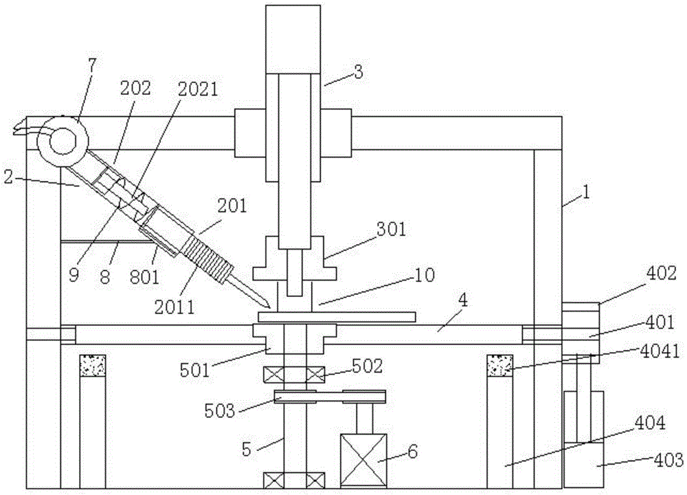
[0003] The purpose of the present invention is to provide a circular track automatic welding device that is convenient for unloading, which solves the problem that the circular contact surface is not easy to weld, and there are many welding points during welding. For welding parts, the parts to be welded are positioned and rotated through the positioning cylinder and the rotating shaft, and the welding parts are rotated to achieve seamless welding; the material receiving plane can be rotated and tilted to facilitate timely and automatic removal of residues and improve production efficiency

Method used


Image

  • Automatic circular-trajectory welding device capable of facilitating discharging

Examples


Embodiment Construction

[0015] See attached figure 1 , a circular track automatic welding device that is convenient for unloading, including a fixed frame 1 and a welding machine 2, the welding machine 2 is arranged on the fixed frame 1, and a positioning cylinder 3 is provided at the middle position of the upper end of the fixed frame 1, and the positioning The bottom of the cylinder 3 is provided with a material receiving plane 4, the two ends of the material receiving plane rotate 401 through the rotating shaft and are arranged on the fixed frame, one end of which extends to the outside of the fixed frame to be provided with a rotating tooth plate 402, the rotating tooth plate is connected with the push cylinder 403, and then A support column 404 is provided below the four corners of the material plane, and a rubber buffer pad 4041 is provided on the upper end of the support column, which is convenient for supporting the material receiving surface after rotation. A rotating shaft 5 is arranged bel...


PUM


Abstract

The invention discloses an automatic circular-trajectory welding device capable of facilitating discharging. The device comprises a fixing frame and a welding machine, wherein a positioning air cylinder is arranged in the middle of the upper end of the fixing frame; a material receiving plane is arranged below the positioning air cylinder; a rotating shaft is arranged below the material receiving plane; upper and lower ends of the rotating shaft are fixed onto the fixing frame through bearings; a transmission wheel is arranged in the middle of the rotating shaft and connected onto an output shaft of a driving motor through a belt; the driving motor is fixedly mounted at the lower end of the fixing frame; the upper end of the rotating shaft extends to the upper end surface of the material receiving plane; a hole matched with the rotating shaft is formed in the material receiving plane; a switch contacted with a welding head is arranged at the front end of the air cylinder. By the aid of the device, the problems that circular contact surfaces are not easy to weld and a lot of welding points exist during welding are solved, the device is reasonable in design structure, a to-be-welded component is positioned and rotated through the positioning air cylinder and the rotating shaft, the component is rotationally welded, and seamless welding is realized; the material receiving plane can be rotationally inclined, so that residues can be cleaned timely, automatically and conveniently.

Description

technical field [0001] The invention relates to the technical field of circular ring welding, in particular to a circular track automatic welding device which is convenient for unloading. Background technique [0002] The side fixing plate part of the existing hydraulic jack is composed of a plane and a plurality of bolt positioning holes. During production and processing, it is necessary to weld several raised small cylinders on one plane, and the surface to be welded is ring-shaped. Because the parts to be welded are relatively small, it is not easy to fix them for welding; The plane is fixed, and then the small cylinder is positioned manually with the aid of auxiliary tools, and then welded. In this way, there are more solder joints on the welding contact surface, which is not conducive to the subsequent painting process. The solder joints need to be polished, which is prone to false welding, and the operation is cumbersome , low production efficiency, poor product quali...

Claims


Application Information

Patent Timeline
Patent Type & Authority Applications(China)
IPC IPC(8): B23K37/00B23K37/02B23K37/04
CPCB23K37/00B23K37/02B23K37/047
Inventor 韦秋林
Owner ANHUI TONGRUN AUTO ACCESSORY
Learn More