A ball valve disassembly tooling and installation and disassembly method

A tooling and ball valve technology, applied in the direction of manufacturing tools, hand-held tools, etc., can solve the problems of labor, damage, and the installation tooling of the ball valve cannot be tightened and stretched at the same time, so as to achieve the effect of saving manpower and reliable process.

Active Publication Date: 2015-11-18
NEWAY VALVE SUZHOU
View PDF12 Cites 0 Cited by
  • Summary
  • Abstract
  • Description
  • Claims
  • Application Information

AI Technical Summary

Problems solved by technology

[0006] For this reason, the technical problem to be solved by the present invention is to overcome the problem that the ball valve installation tooling in the prior art cannot realize the functions of simultaneously tightening and stretching, and that it is laborious and has the risk of damage during use, so as to provide a safe , labor-saving, easy to use, and can realize the simultaneous tensioning and stretching functions of the online ball valve disassembly tooling
[0007] Another technical problem to be solved by the present invention is to overcome the problem that the installation tooling of the ball valve in the prior art cannot realize the functions of tensioning and pushing at the same time, and that it is laborious and has the risk of damage during use, so as to provide a safe and labor-saving The installation method of the on-line ball valve disassembly and assembly tool that is easy to use and can realize the functions of tensioning and spreading at the same time
[0008] Another technical problem to be solved by the present invention is to overcome the problem that the installation tooling of the ball valve in the prior art cannot realize the functions of tensioning and pushing at the same time, and that it is laborious and has the risk of damage during use, so as to provide a safe and labor-saving The disassembly method of the online ball valve disassembly and assembly tool that is easy to use and can realize the functions of tensioning and spreading at the same time

Method used


Image

  • A ball valve disassembly tooling and installation and disassembly method
  • A ball valve disassembly tooling and installation and disassembly method
  • A ball valve disassembly tooling and installation and disassembly method

Examples


Embodiment 1

[0045] This embodiment provides a ball valve disassembly tooling, such as Figure 4 As shown, it includes: a tensioning device for tightening the fixture 3 and a stretching device for stretching the spring seat 5, and the tensioning device and the stretching device cooperate to realize the spring seat 5 and the spring seat 5. opposite movement of the holder 3,

[0046] The tensioning device includes a rotating device 30, a screw 12 connected to the rotating device 30 and driven to rotate by the rotating device 30, and a moving part 11 that cooperates with the screw 12 through a first matching structure. The moving part 11 is connected with the fixer 3 through the second matching structure, and the moving part 11 drives the fixer 3 away from the spring seat 5 under the drive of the rotation of the screw 12;

[0047] The spreading device includes a power device 60 , a push rod 15 connected to the power device 60 and driven by the power device 60 , and an abutting portion 14 , o...

Embodiment 2

[0056] This embodiment provides a method for installing a top-mounted ball valve using the disassembly tooling described in Embodiment 1, which includes the following steps:

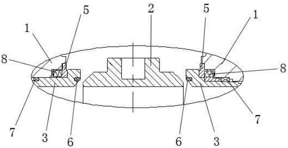
[0057] S1: Put the first seal 7, spring 8, spring seat 5, retainer 3, second seal 6, and ball 2 into the valve, according to figure 2 The state shown is installed;

[0058] S2: Fix the moving part 11 on the holder 3 through the second matching structure, such as Figure 5 As shown, the screw rod 12 and the rotating device 30 are fixed through the third matching structure, and the abutting portion 14 is aligned with the spring seat 5, and the tensioning device fixer 3 is fixedly connected, such as connected by screws, and stretched apart. The device abuts against the spring seat 5 to complete the installation of disassembly tooling; it should be pointed out that at this time, the tensioning device and the spreading device can be placed at a certain angle along the circular inner cavity of the valve body...

Embodiment 3

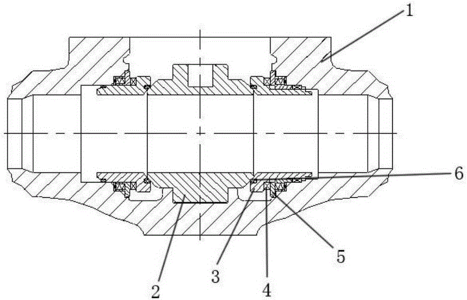
[0063] This embodiment provides a method for disassembling the top-mounted ball valve using the disassembly tooling described in Embodiment 1. The installed top-mounted ball valve is as follows: figure 1 shown, including the following steps:

[0064] S1: Fix the moving part 11 on the holder 3 through the second matching structure, such as Figure 5 As shown, the screw rod 12 and the rotating device 30 are fixed through the third matching structure, and the abutting portion 14 is aligned with the spring seat 5, and the tensioning device is fixedly connected with the fixer 3, such as by screw connection, supporting The opening device abuts against the spring seat 5 to complete the installation of the disassembly tooling;

[0065]S2: Start the rotating device 30 to drive the screw 12 to rotate, and drive the moving part 11 and the fixer 3 fixed with the moving part 11 away from the spring seat 5; at the same time start the power device 60 to drive the abutting part 14 Connected...


PUM


Abstract

The invention provides a ball valve installing and dismantling tool which comprises a tensioning device used for tensioning a fixer (3) and a stretching device used for stretching a spring seat (5) open, wherein the tensioning device and the stretching device cooperate to achieve opposite movement of the spring seat (5) and the fixer (3), the tensioning device comprises a rotating device (30), a screw (12) and a movable part (11), and the movable part (11) is connected with the fixer (3) through a second matching structure; the stretching device comprises a power device (60), an ejector rod (15) and an abutting part (14), one end of the abutting part (14) is connected with the ejector rod (15), and the other end of the abutting part abuts against the spring seat (5). The ball valve installing and dismantling tool can save labor, is convenient to use and can be used online. In addition, the invention provides a ball valve installing and dismantling method.

Description

technical field [0001] The invention relates to a ball valve disassembly tooling and an installation and disassembly method, belonging to the technical field of valve installation. Background technique [0002] Ball valve has become one of the most widely used valves due to its reliable sealing, simple structure and convenient maintenance. Compared with the side-mounted ball valve, the top-entry ball valve has the advantages of fewer leakage points and less influence of pipeline stress on it. At present, the top-entry ball valve is widely used in LNG pipelines, LNG carriers and receiving stations. Therefore, many domestic valve manufacturers All have invested a lot of manpower, material resources and financial resources to study the top entry ball valve. [0003] Such as figure 1 As shown, a top-entry ball valve researched by the applicant mainly includes a valve body 1 with a circular inner cavity, a ball 2 placed in the valve body, a retainer 3 sealingly connected with t...

Claims


Application Information

Patent Timeline
Patent Type & Authority Patents(China)
IPC IPC(8): B25B27/24
CPCB25B27/24
Inventor 周金荣刘长福王建华
Owner NEWAY VALVE SUZHOU
Why Eureka
Try Eureka