A shunt plate fixing mechanism

A fixing mechanism and splitter plate technology, applied in the field of splitter plate fixing mechanism, can solve problems such as poor convenience of use

Active Publication Date: 2016-08-17
SUZHOU HTS MOLD
View PDF4 Cites 0 Cited by
  • Summary
  • Abstract
  • Description
  • Claims
  • Application Information

AI Technical Summary

Problems solved by technology

[0002] The existing splitter plate fixing mechanism is to process screw teeth on the screw pad 3, the screw 2 passes through the splitter plate 1 and is screwed onto the screw pad 3, and there is a space in the middle of the screw 2, so that the screw pad 3 has However, when the screw 2 slips or breaks, it needs to be reprocessed on the replacement screw 2 to avoid the space, and the convenience of use is poor.

Method used


Image

  • A shunt plate fixing mechanism
  • A shunt plate fixing mechanism

Examples


Embodiment Construction

[0011] The preferred embodiments of the present invention will be described in detail below in conjunction with the accompanying drawings, so that the advantages and features of the present invention can be more easily understood by those skilled in the art, so as to define the protection scope of the present invention more clearly.

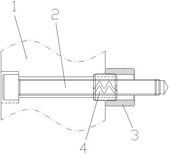
[0012] see figure 2 , the embodiment of the present invention includes:

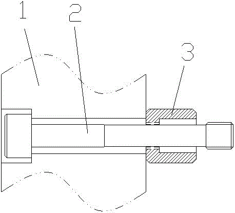
[0013] A diverter plate fixing mechanism, including screws 2, screw pads 3 and open spring fixing rings 4; the diverter plate 1 is provided with screw holes, and the screws 2 pass through the screw holes and protrude from the diverter plate 1 The screw pad 3 is provided with a through hole, and the screw pad 3 is set on the screw 2 outside the manifold 1; the opening spring retainer 4 is set on the screw 2; the opening One end of the spring fixing ring 4 is embedded in the screw hole of the splitter plate 1, and the other end is embedded in the screw pad 3, so that the sc...


PUM


Abstract

The invention discloses a shunt plate fixing mechanism including: a screw, a screw heel block and an opening spring fixing ring; the screw heel block is provided with a through hole, and sleeves the screw; and the opening spring fixing ring is arranged between the screw and the screw heel block. By the way, the shunt plate fixing mechanism enables the screw block to be firmly fixed in the screw, and the screw heel block has the activity space, so that the screw is in no need of processing for empty avoiding.

Description

technical field [0001] The invention relates to the field of fixing mechanisms, in particular to a splitter plate fixing mechanism. Background technique [0002] The existing splitter plate fixing mechanism is to process screw teeth on the screw block 3, the screw 2 passes through the splitter plate 1 and is screwed onto the screw block 3, and there is a space in the middle of the screw 2, so that the screw block 3 has However, when the screw 2 slips or breaks, it needs to be reprocessed on the replacement screw 2 to avoid the space, and the convenience of use is poor. Contents of the invention [0003] The technical problem mainly solved by the present invention is to provide a fixing mechanism for the manifold, which can firmly fix the screw spacer on the screw, and the screw spacer has a movable space, and the screw does not need to be processed to avoid the space. [0004] In order to solve the above technical problems, a technical solution adopted by the present inve...

Claims


Application Information

Patent Timeline
Patent Type & Authority Patents(China)
IPC IPC(8): B29C45/27
CPCB29C45/2701
Inventor 严杰
Owner SUZHOU HTS MOLD
Why Eureka
Try Eureka