
Engineering machinery and fuel system thereof

A technology of fuel system and construction machinery, applied in the direction of charging system, mechanical equipment, engine components, etc., to achieve convenient disassembly and maintenance, broad market prospects, and avoid the effect of controlling wiring harness

Inactive Publication Date: 2014-10-08
崔光铸
View PDF0 Cites 2 Cited by
  • Summary
  • Abstract
  • Description
  • Claims
  • Application Information

AI Technical Summary

Problems solved by technology

And if the fuel oil freezes, the above devices are difficult to solve

Method used


Image

  • Engineering machinery and fuel system thereof
  • Engineering machinery and fuel system thereof

Examples


Embodiment Construction

[0025] In order to make the purpose, technical solutions and advantages of the embodiments of the present invention more clear, specific embodiments will be described in detail below with reference to the accompanying drawings.

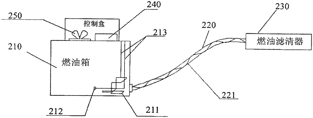
[0026] figure 1 The structural diagram of the fuel system provided by the present invention, as shown in the figure, the fuel system of the engineering machinery of the present invention includes a fuel tank 210, a fuel delivery pipe 220 and a fuel filter 230 connected in sequence, wherein the fuel tank 210 An electric heating device 211 is arranged inside the oil outlet.

[0027] In the present invention, the electric heating device 211 is arranged inside the oil outlet, so that the fuel near the oil outlet can be thawed first, so that the fuel can be supplied as soon as possible.

[0028] The inside of the fuel delivery pipe 220 is provided with a heating wire 221 so as to heat the fuel in the fuel delivery pipe 220 and prevent the fuel pipe from b...


PUM


Abstract

The invention provides engineering machinery and a fuel system thereof. The fuel system comprises a fuel tank, a fuel delivery pipe and a fuel filter which are in sequential connection, wherein an electric heater unit is arranged on the inner side of a fuel outlet of the fuel tank. The engineering machinery and the fuel system can complete the cold boot of engineering machinery vehicles in a lower cost, convenient and efficient manner.

Description

technical field [0001] The invention relates to engineering machinery, in particular to an engineering machinery and its fuel system. Background technique [0002] Construction machinery, such as loaders, excavators, etc., are widely used in engineering fields such as construction, roads, mines, and ports. [0003] Existing loaders are generally driven by diesel fuel, and the fuel tank is exposed outside, which is greatly affected by the external temperature. Therefore, the difficulty of starting the engine in winter has always been one of the factors affecting the operation of the loader in winter in the northern region. The reason for the difficulty in starting is not only the capacity of the battery In addition to the problem, the engine temperature is too low, another possible reason is that the fuel is frozen, especially when the diesel oil used is poor, it is more serious. [0004] At present, there are air intake heating devices (such as hot or flame preheating) and ...

Claims


Application Information

Patent Timeline
Patent Type & Authority Applications(China)
IPC IPC(8): F02M37/00F02M31/125
Inventor 崔光铸陈辉
Owner 崔光铸
Learn More