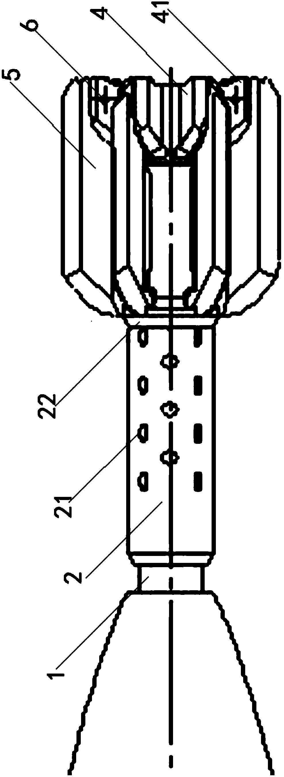
Variable pneumatic layout structure for projectile body

An aerodynamic layout and projectile technology, which is applied in the direction of projectiles, offensive equipment, weapon types, etc., can solve the problems of unsatisfactory, increased drag coefficient of large tail aerodynamic layout projectiles, and low accuracy of projectile correction, so as to achieve reduction control Effects of system impact, guaranteed range, and corrected accuracy requirements

Active Publication Date: 2014-10-08
BEIJING INSTITUTE OF TECHNOLOGYGY +1
View PDF5 Cites 15 Cited by
  • Summary
  • Abstract
  • Description
  • Claims
  • Application Information

AI Technical Summary

Benefits of technology

This new design allows for better airflow while maintaining stable flight characteristics without adding extra weight or making it harder on certain parts that are important during launches. It uses an asymmetrical arrangement where there're two types of wings: one with larger rear ends than usual (the big-tail) and another smaller wing called the small back end. By jumping between these wings when they hit each other, the space around them becomes more open up allowing fluid flow within the device. Additionally, this innovative feature helps stabilizing the ball after being launched from its trajectory.

Problems solved by technology

This patented problem addressed in this patents relates to improving the performance of guide systems used during military operations due to their limitations such as poor flight precision or excessive fuel usage. These issues include instability caused by changes in external factors like temperature fluctuations (T), shock waves from explosions, etc., while current designs suffer drawbacks including limited dynamic stabilizing capacity, difficulty achieving stable firing angles, complicated structures requiring expensive fabrication processes, and lacking flexibility in adjustments based upon mission goals.

Method used


Image

  • Variable pneumatic layout structure for projectile body
  • Variable pneumatic layout structure for projectile body
  • Variable pneumatic layout structure for projectile body

Examples


Embodiment Construction

[0047] The following describes the present invention in detail, and the features and advantages of the present invention will become more clear and definite along with these descriptions.

[0048] The word "exemplary" is used exclusively herein to mean "serving as an example, embodiment, or illustration." Any embodiment described herein as "exemplary" is not necessarily to be construed as superior or better than other embodiments. While various aspects of the embodiments are shown in drawings, the drawings are not necessarily drawn to scale unless specifically indicated.

[0049] The front end in the present invention refers to the direction that missile head points to, and rear end is opposite to front end, and front end and rear end are two directions along missile body axis, from figure 1with figure 2 It can be seen that the front end refers to the left side in the figure, and the rear end refers to the right side in the figure.

[0050] In a preferred embodiment of the...


PUM


Abstract

The invention discloses a variable pneumatic layout structure for a projectile body, and particularly relates to a variable pneumatic layout structure capable of combining the stability of the projectile body in a free flight stage and the hitting accuracy of the projectile body in a correction stage. A variable pneumatic shape scheme is adopted; an empennage is locked into a small-empennage pneumatic layout in an original free flight section of a trajectory, so that the flight stability of the projectile body can be ensured, resistance can be reduced, and the range can be prolonged; in a tail section of the trajectory, the empennage is unfolded into a large-empennage pneumatic layout, so that the static stability of the projectile body is improved, projectile body attitude angle oscillation caused by surging force can be rapidly converged, and the requirements of a control system can be met. According to the variable pneumatic layout structure for the projectile body, the advantages of a fixed-empennage pneumatic layout and the large-empennage pneumatic layout are combined, so that a requirement on the static stability of the projectile body can be met, the influence of the projectile body attitude angle oscillation caused by surging force on the control system can be reduced, the range can be ensured, and a requirement on the correction accuracy can also be met; multiple range tests show that the scheme is feasible.

Description


Claims


Application Information

Patent Timeline
Owner BEIJING INSTITUTE OF TECHNOLOGYGY
Why Eureka
Try Eureka