
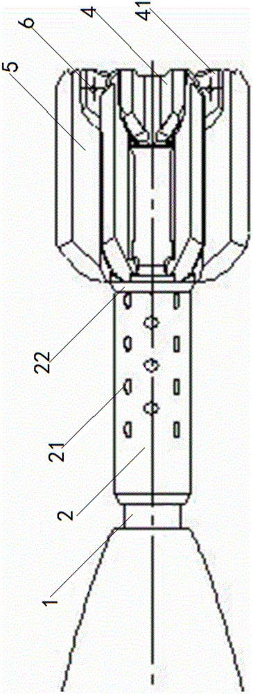
Variable aerodynamic layout structure of projectile

An aerodynamic layout and projectile technology, which is applied to projectiles, offensive equipment, weapon types, etc., can solve the problems of insufficiency, increase in the drag coefficient of the large tail aerodynamic layout, and low correction accuracy of the projectile, and achieve reduced control. System impact, guaranteed range, and effect of correction accuracy requirements

Active Publication Date: 2015-09-30
BEIJING INSTITUTE OF TECHNOLOGYGY +1
View PDF5 Cites 1 Cited by
  • Summary
  • Abstract
  • Description
  • Claims
  • Application Information

AI Technical Summary

Problems solved by technology

However, compared with the aerodynamic layout of the fixed tail, the drag coefficient of the projectile with the aerodynamic layout of the large tail increases, and the range decreases, which cannot meet the requirements of simple correction of the projectile range.
[0006] Due to the existence of the above-mentioned problems, the present inventor conducted in-depth research on the existing aerodynamic layout structure of the projectile body in order to solve the problems of low correction accuracy and reduced firing range of the projectile body

Method used


Image

  • Variable aerodynamic layout structure of projectile
  • Variable aerodynamic layout structure of projectile
  • Variable aerodynamic layout structure of projectile

Examples


Embodiment Construction

[0047] The following describes the present invention in detail, and the features and advantages of the present invention will become more clear and definite along with these descriptions.

[0048] The word "exemplary" is used exclusively herein to mean "serving as an example, embodiment, or illustration." Any embodiment described herein as "exemplary" is not necessarily to be construed as superior or better than other embodiments. While various aspects of the embodiments are shown in drawings, the drawings are not necessarily drawn to scale unless specifically indicated.

[0049] The front end in the present invention refers to the direction that missile head points to, and rear end is opposite to front end, and front end and rear end are two directions along missile body axis, from figure 1and figure 2 It can be seen that the front end refers to the left side in the figure, and the rear end refers to the right side in the figure.

[0050] In a preferred embodiment of the ...


PUM


Abstract

The invention discloses a variable pneumatic layout structure for a projectile body, and particularly relates to a variable pneumatic layout structure capable of combining the stability of the projectile body in a free flight stage and the hitting accuracy of the projectile body in a correction stage. A variable pneumatic shape scheme is adopted; an empennage is locked into a small-empennage pneumatic layout in an original free flight section of a trajectory, so that the flight stability of the projectile body can be ensured, resistance can be reduced, and the range can be prolonged; in a tail section of the trajectory, the empennage is unfolded into a large-empennage pneumatic layout, so that the static stability of the projectile body is improved, projectile body attitude angle oscillation caused by surging force can be rapidly converged, and the requirements of a control system can be met. According to the variable pneumatic layout structure for the projectile body, the advantages of a fixed-empennage pneumatic layout and the large-empennage pneumatic layout are combined, so that a requirement on the static stability of the projectile body can be met, the influence of the projectile body attitude angle oscillation caused by surging force on the control system can be reduced, the range can be ensured, and a requirement on the correction accuracy can also be met; multiple range tests show that the scheme is feasible.

Description

technical field [0001] The invention relates to the field of missile control, in particular to a variable aerodynamic layout structure of a missile body. Background technique [0002] In modern warfare, the use of conventional weapons platforms to develop low-cost smart guided missiles can not only greatly improve the combat effectiveness of conventional weapons, but also equip a large number of troops. It has become one of the development directions of guided missiles in various countries. At present, with the development of electronic technology, optoelectronic technology, micro-processing technology and guidance technology, the miniaturization of guidance components and the improvement of high overload resistance have made the technical conditions for the guidance of conventional missiles more mature. The scale has also gradually expanded, and its role in the war has become more and more important. [0003] The simple modified projectile controlled by the pulse engine ca...

Claims


Application Information

Patent Timeline
Patent Type & Authority Patents(China)
IPC IPC(8): F42B10/06F42B10/20
Inventor 杨哲唐义平林德福郑多
Owner BEIJING INSTITUTE OF TECHNOLOGYGY
Learn More