Wireless link apparatus

a technology of wired link and wired cable, which is applied in the direction of digital transmission, spatial transmit diversity, diversity/multi-antenna system, etc., can solve the problems of low transmission rate, simple structure, and reduced snr in the same transmission rang

Inactive Publication Date: 2014-09-25
ELECTRONICS & TELECOMM RES INST
View PDF7 Cites 2 Cited by
  • Summary
  • Abstract
  • Description
  • Claims
  • Application Information

AI Technical Summary

Benefits of technology

[0024]Moreover, due to maintenance of a stable wireless link, use of a simple transceiver configuration can obtain availability approximate to that of lined link.

Problems solved by technology

The loss caused by rainfall leads to reduce SNR in the same transmission range because of attenuation of signals.
This method has a simple structure but low transmission rate.
This method, as illustrated in FIG. 2, needs many additional blocks and has a complicated structure.
Meanwhile, the rainfall loss may be generated not only on a path but by increase of fading component.

Method used


Image

  • Wireless link apparatus
  • Wireless link apparatus
  • Wireless link apparatus

Examples


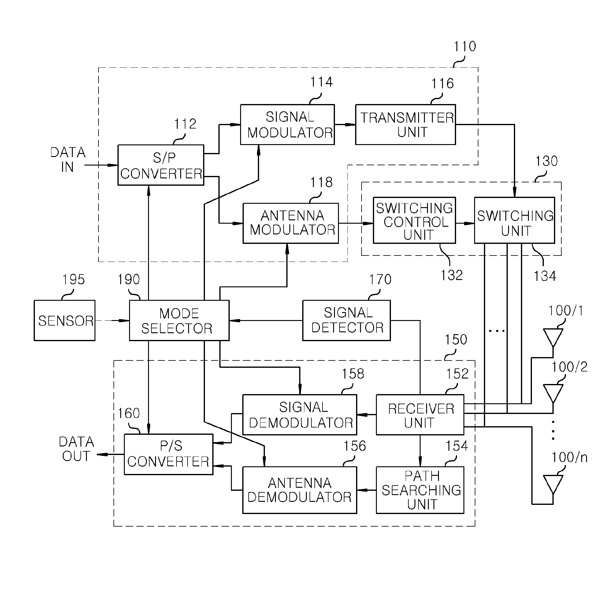
Embodiment Construction

[0029]Embodiments of the present invention are described herein, including the best mode known to the inventors for carrying out the invention. Variations of those preferred embodiments may become apparent to those of ordinary skill in the art upon reading the foregoing description. The inventors expect skilled artisans to employ such variations as appropriate, and the inventors intend for the invention to be practiced otherwise than as specifically described herein. Accordingly, this invention includes all modifications and equivalents of the subject matter recited in the claims appended hereto as permitted by applicable law. Moreover, any combination of the above-described elements in all possible variations thereof is encompassed by the invention unless otherwise indicated herein or otherwise clearly contradicted by context.

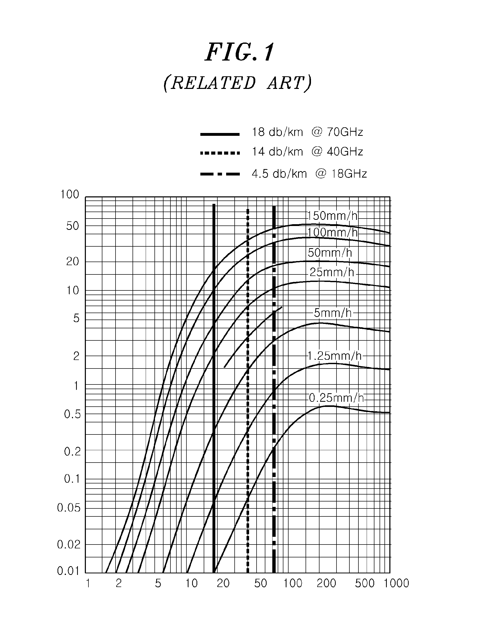
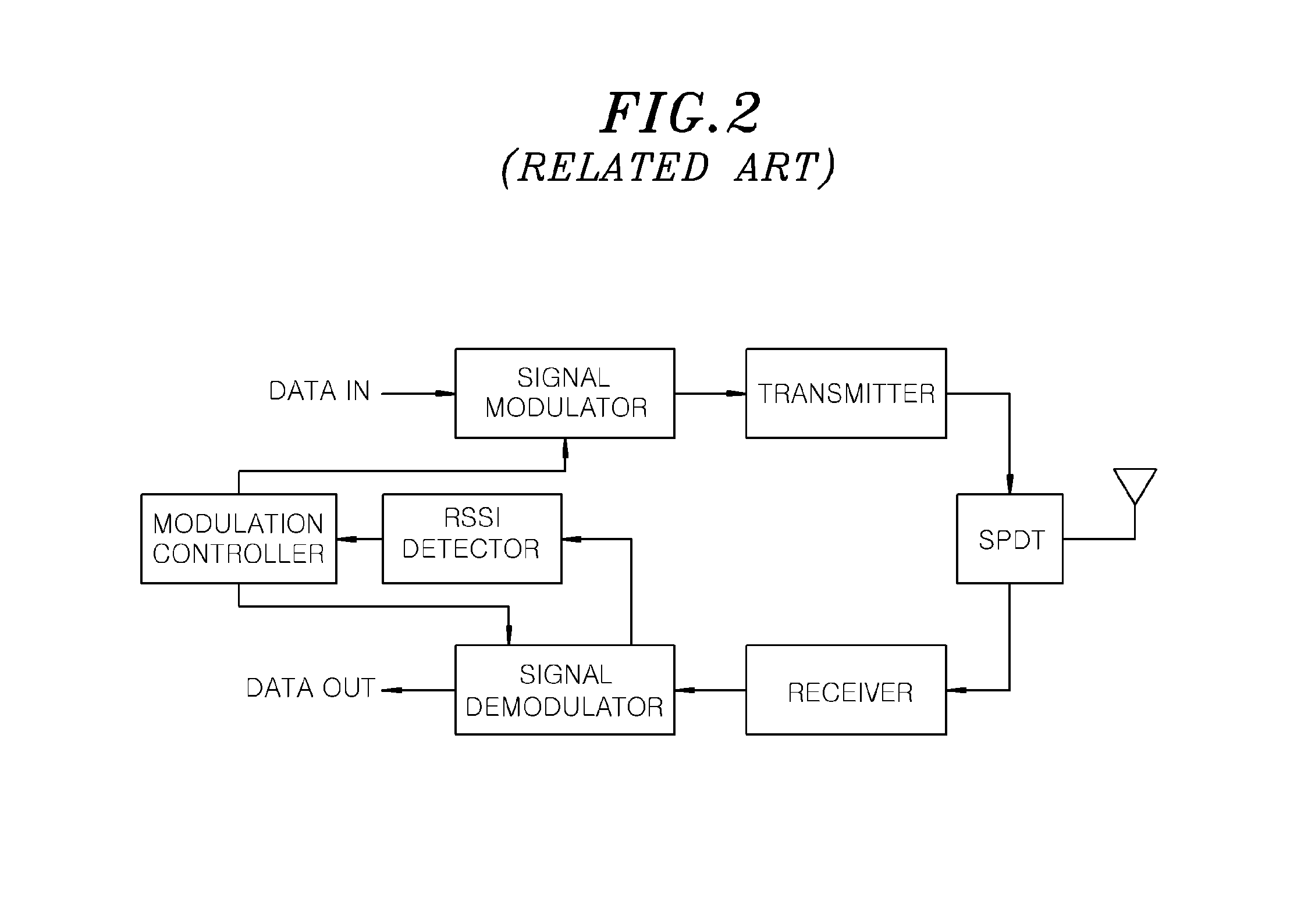
[0030]In the following description of the present invention, if the detailed description of the already known structure and operation may confuse the subject ...


PUM


Abstract

A wireless link apparatus includes a plurality of antennas; a signal detector configured to calculate SNR based on a signal received from at least one of the plurality of antennas; and a mode selector configured to determine the number of an antenna to be used in modulation method and signal transmission by comparing the calculated SNR with a preset critical value. Further, the wireless link apparatus includes a transmitter configured to modulate a signal in the modulation method determined by the mode selector and transmit the modulated signal using an antenna corresponding to the determined number of the antennas.

Description

CROSS-REFERENCE TO RELATED APPLICATIONS[0001]The present invention claims priority of Korean Patent Application No. 10-2013-0030883, filed on Mar. 22, 2013, which is incorporated herein by reference.FIELD OF THE INVENTION[0002]The present invention relates to a fixed Line-Of-Sight (LOS) wireless link apparatus using high frequency, and more particularly, to a wireless link apparatus for transmitting a preset quantity of data at high rate regardless of environment such as weather.BACKGROUND OF THE INVENTION[0003]Conventional wireless network markets need a high-speed backhaul network to maintain a large capacity / high speed communication network as various high-speed wireless data services such as 4G mobile communications, 802.11n / ac, wireless LAN, etc., are developed.[0004]Moreover, for explosive increase of data in a cell, small cell-centered configurations are increased to solve the problem of the explosive increased quantity of data. To support these network architectures, demands...

Claims


Application Information

Patent Timeline
Patent Type & Authority Applications(United States)
IPC IPC(8): H04B7/04
CPCH04B7/0404H04B7/0602H04B7/005H04L27/00
Inventor KIM, KWANG SEONKANG, MIN SOOKIM, BONG-SUBYUN, WOO JIN
Owner ELECTRONICS & TELECOMM RES INST
Why Eureka
Try Eureka