Method for guaranteeing measuring range of laser range measurer and improving measuring precision

A laser range finder and measurement accuracy technology, applied in the field of laser measurement, can solve the problems of longer alignment time than measurement time, shortened measurement range, lower measurement accuracy, etc., to reduce output optical power drop and temperature drift, and ensure range and accuracy, avoiding the effect of large changes

Inactive Publication Date: 2014-01-08
罗江临
View PDF6 Cites 2 Cited by
  • Summary
  • Abstract
  • Description
  • Claims
  • Application Information

AI Technical Summary

Problems solved by technology

[0002] At present, the known visible laser range finder uses the same laser beam for alignment and measurement. Since the temperature of the semiconductor laser rises with the prolongation of the working time, the output optical power decreases with the rise of the temperature, and the temperature The rise makes the laser wavelength redshift, which easily leads to shortened measurement and decreased measurement accuracy
[0003] In the measurement work, the alignment time is often longer than the measurement time, especially when the distance is far or under the sun, it often takes more time to align, while the measurement time is only a few tenths of a second, using a single laser beam for alignment And measurement, due to the long-term heavy load work of the laser, the temperature of the laser rises rapidly, resulting in shortened measurement range and decreased measurement accuracy, which also shortens the service life of the laser

Method used


Image

  • Method for guaranteeing measuring range of laser range measurer and improving measuring precision
  • Method for guaranteeing measuring range of laser range measurer and improving measuring precision
  • Method for guaranteeing measuring range of laser range measurer and improving measuring precision

Examples


Embodiment Construction

[0017] In order to facilitate the understanding of those skilled in the art, the structural principles of the present invention will be further described in detail below in conjunction with specific embodiments and accompanying drawings.

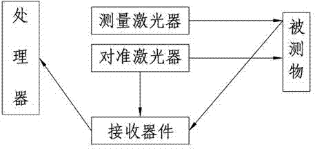
[0018] like figure 1 As shown, a method to ensure the range of the laser rangefinder and improve the measurement accuracy, it includes the following steps:

[0019] The first step is to install two lasers on the laser rangefinder. The two lasers use the same signal source to generate laser beams with different wavelengths but the same signal;

[0020] In the second step, one laser is used for alignment and the other laser is used for measurement. The emission power of the alignment laser is smaller than that of the measurement laser, and the spot is larger than the measurement laser;

[0021] In the third step, only the alignment laser is turned on during alignment, which emits the laser with the same signal source as the measurement laser...


PUM


Abstract

The invention discloses a method for guaranteeing the measuring range of a laser range measurer and improving the measuring precision. The method comprises the following steps of mounting two laser devices on the laser range measurer, wherein the two laser devices use the same signal source and respectively generate laser beams which have different wavelengths and same signals; enabling one laser device to implement alignment and the other laser device to implement measurement, wherein the emission power of the alignment laser device is smaller than that of the measurement laser device, and the spot ratio of the alignment laser device is larger than that of the measurement laser device; during alignment, only starting the alignment laser device; after the alignment is finished, controlling the measurement laser device to implement emission, and shutting down the alignment laser device, and sampling an alignment laser signal which is not subjected to external transmission through a synchronous control receiver; enabling the alignment laser device and the measurement laser device to work and take a rest alternately. According to the method for guaranteeing the measuring range of the laser range measurer and improving the measuring precision, the temperatures of the laser devices always have no large change, so that the aims of guaranteeing the maximum measuring range and keeping the measuring precision are fulfilled; meanwhile, a measurement laser signal is calibrated through the alignment laser signal, and the measuring precision is improved.

Description

technical field [0001] The invention relates to a laser measurement method, in particular to a method for ensuring the range of a laser range finder and improving measurement accuracy. Background technique [0002] At present, the known visible laser range finder uses the same laser beam for alignment and measurement. Since the temperature of the semiconductor laser rises with the prolongation of the working time, the output optical power decreases with the rise of the temperature, and the temperature The rise makes the laser wavelength redshift, which easily leads to shortened measurement and decreased measurement accuracy. [0003] In the measurement work, the alignment time is often longer than the measurement time, especially when the distance is far or under the sun, it often takes more time to align, while the measurement time is only a few tenths of a second, using a single laser beam for alignment And measurement, due to the long-term heavy load of the laser, the te...

Claims


Application Information

Patent Timeline
IPC IPC(8): G01C3/02
CPCG01S7/497G01S17/08G01S2007/4977
Inventor 罗江临
Owner 罗江临
Why Eureka
Try Eureka