laser printer

A technology of laser printers and powder cartridges, applied in optics, electrography, instruments, etc., can solve problems such as being easily collided by external forces or other objects, the electrical connection performance of the contact pin 15 being degraded, and the laser printer being unable to be used normally. The effect of increasing stiffness, avoiding deformation or breakage, improving durability and stabilizing performance

Active Publication Date: 2017-09-12
PRINT RITE UNICORN IMAGE PROD CO LTD
View PDF9 Cites 0 Cited by
  • Summary
  • Abstract
  • Description
  • Claims
  • Application Information

AI Technical Summary

Problems solved by technology

[0007] However, since the contact pin 15 protrudes from the base so as to be better electrically connected to the electrical contacts, but when the powder container 11 is taken out from the powder container mounting position, the contact pin 15 will always be exposed on the base 14, so the exposed contact pin 15 is easily polluted by the residual carbon powder in the movement, so that the electrical connection performance of the contact pin 15 is reduced. Deformation or breakage of the stylus leads to failure of the entire laser printer

Method used


Image

  • laser printer
  • laser printer
  • laser printer

Examples


Embodiment Construction

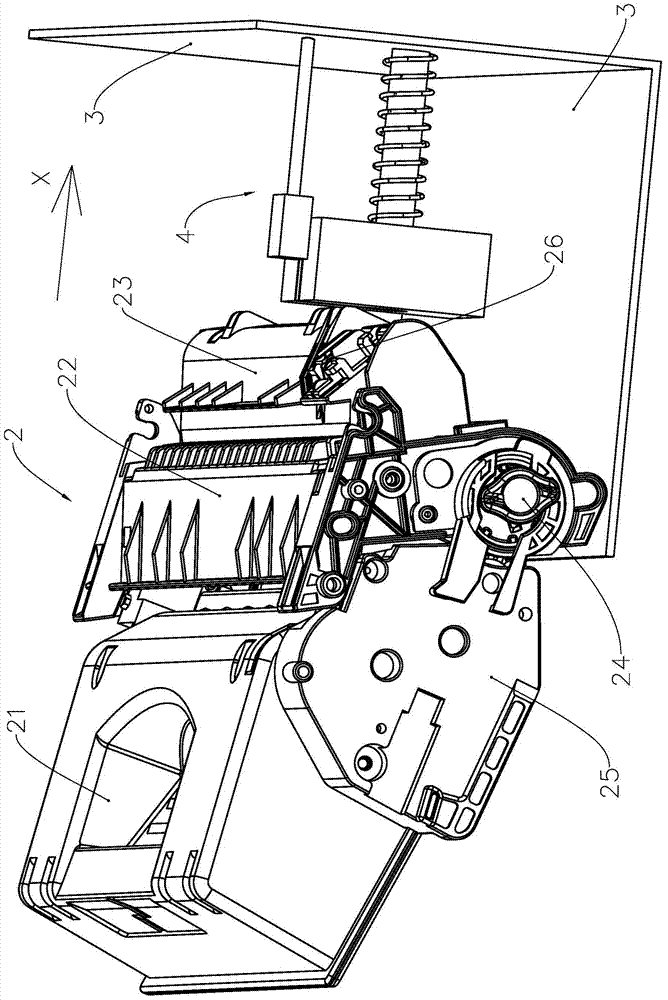
[0037] refer to image 3 , image 3 It is the structure diagram when the powder box 2 and the stylus mechanism 4 cooperate in the laser printer. The process box 2 includes a developing unit 21 and a drum unit 22. The housing of the developing unit 21 encloses a toner accommodating cavity containing carbon powder. A stirring frame, a powder feeding roller, a developing roller and a powder output knife are installed in the toner accommodating cavity. and other components, the shell of the drum unit 22 encloses a waste toner holding chamber 23 containing waste toner, and the waste toner holding chamber 23 is equipped with parts such as a photosensitive drum, a charging roller and a cleaning blade. On one side of the photosensitive drum, a driving force receiver 24 is installed.

[0038] On one side of developing unit 21, side cover 25 is installed, and a plurality of transmission gears are installed in the space between side cover 25 and the casing of developing unit 21, and a ...


PUM


Abstract

The invention provides a laser printer. A powder box installation position for installing the powder box is arranged in the housing. A contact pin mechanism is installed at the end of the powder box installation position. The contact pin mechanism includes a base, and the base is fixedly connected to the powder box. In terms of position, a plurality of contact pins and a circuit board are arranged on the base, and the plurality of contact pins are electrically connected to the circuit board. The contact pin mechanism also includes a protection part, a limit part and a spring, and the protection part is provided with a plurality of grooves , the groove has an opening, and each contact pin is installed into a groove through the opening, the protective piece cooperates with the limiting piece, the protective piece can slide along the limiting piece in the extending direction of the groove, the first end of the spring is connected to the The protective piece abuts, and the second end of the spring abuts against the installation position of the powder box. The groove supports and protects the stylus, avoiding deformation or breakage when in contact with the electrical contacts, thereby improving the durability and stability of the stylus mechanism.

Description

technical field [0001] The invention relates to the field of electronic imaging printers, in particular to a laser printer equipped with a stylus mechanism. Background technique [0002] An electronic imaging printer is a device that uses the principle of electrophotographic imaging to form images on recording materials. Image imaging devices include copiers, printers, fax machines, and the like. Process cartridges used in image forming equipment are generally divided into two types, one is an integrated toner cartridge that includes a developing roller and a photosensitive drum as a developing device, and the other is a split toner cartridge that separates the photosensitive drum to the outside. Both toner cartridges are detachably mounted into the main body of the image forming apparatus. [0003] A typical image imaging device is a laser printer. Laser printers are one of the most widely used image imaging devices at present. Laser printers use the physical and chemical ...

Claims


Application Information

Patent Timeline
Patent Type & Authority Patents(China)
IPC IPC(8): G03G15/00
Inventor 何永刚
Owner PRINT RITE UNICORN IMAGE PROD CO LTD
Why Eureka
Try Eureka