Method for pulling in restoration pipe, and restored pipeline

A technology for repairing pipes and manholes. It is used in sewer pipeline systems, pipeline laying and maintenance, pipes/pipe joints/fittings, etc. It can solve problems such as reduced load bearing capacity, insufficient drainage capacity, and road subsidence.

Active Publication Date: 2015-07-08
KANA FURETSUKUSU KOOHOREESHON
View PDF6 Cites 0 Cited by
  • Summary
  • Abstract
  • Description
  • Claims
  • Application Information

AI Technical Summary

Problems solved by technology

[0002] The sewer pipes buried in the soil for a long time may reduce the load bearing capacity and cause road subsidence or insufficient drainage capacity.

Method used


Image

  • Method for pulling in restoration pipe, and restored pipeline
  • Method for pulling in restoration pipe, and restored pipeline
  • Method for pulling in restoration pipe, and restored pipeline

Examples


Embodiment approach 1

[0061] Hereinafter, the present invention will be described in detail based on the embodiments shown in the drawings.

[0062] [1] Inspection of drains

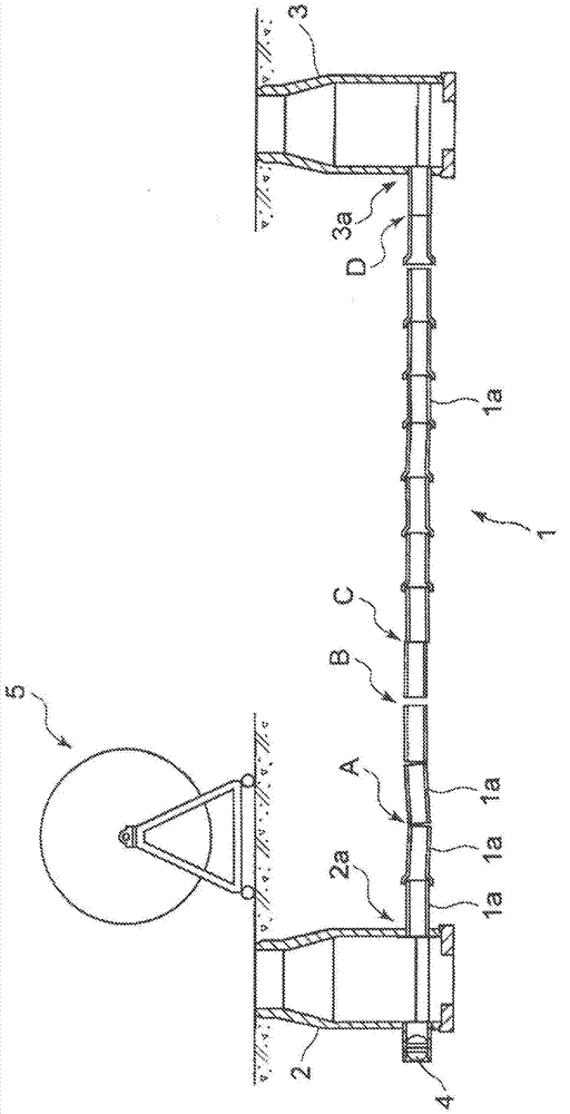
[0063] figure 1 Shown is an aging piped drainage path to which the repair pipe introduction method of the present invention is applied.

[0064] figure 1 Among them, the drainage channel 1 is formed by connecting a plurality of concrete drainage pipes 1a and burying them in soil. One end portion of the drainage passage 1 is connected to, for example, a lower opening portion 2 a provided at a lower portion of the upstream-side access hole 2 . The other end portion of the drainage passage 1 is connected to a lower opening portion 3 a provided at a lower portion of the downstream-side access hole 3 .

[0065] When repairing the above-mentioned drainage channel 1, the inspection of the drainage channel 1 is performed first.

[0066] Specifically, a high-pressure cleaning vehicle is arranged, and the inside of the drainage ...

Deformed example 1

[0157] In Modification 1, the diagnosis process and the excavation process are performed before the simulation introduction process of the first embodiment.

[0158] In the diagnosis process, in order to detect a narrow part in the drainage channel 1 , a diagnostic tool, which will be described later, is passed through the drainage channel 1 . In addition, in the diagnosis process, it is preferable to insert the camera from the rear of the diagnosis tool, and to operate while checking the passing state of the diagnosis tool.

[0159] In the excavation step, an excavator is inserted into the narrow portion in the drainage channel 1 detected by the diagnosis step, and the inner wall of the drainage channel 1 is cut to expand the narrow portion.

[0160] [1] Diagnostic tool

[0161] Figure 11 It is an external view of the diagnostic tool 60 of the modification 1. FIG. Figure 11 Among them, the diagnostic tool 60 of Modification 1 has a tool body 61 made of an iron or steel m...

Embodiment approach 2

[0187] [1] Inspection of drains

[0188] Figure 13 Shown is an aging piped drainage path to which the pipe repairing method of the present invention is applied.

[0189] Figure 13 Among them, the drainage path 201 is formed by connecting a plurality of concrete drainage pipes 201a and burying them in soil. One end portion of the drainage passage 201 is connected to, for example, a lower opening portion 202a provided at the lower portion of the inspection hole 202 on the most upstream side. The other end portion of the drainage passage 201 is connected to a lower opening portion 203 a provided at the lower portion of the downstream side access hole 203 .

[0190] When repairing the above-mentioned drainage channel 201, an inspection of the drainage channel 201 is performed first.

[0191] Specifically, a high-pressure cleaning vehicle is arranged in the vicinity of the manhole 203 on the downstream side, and the inside of the drainage passage 201 is cleaned with high-pres...


PUM


Abstract

Provided is a restoration pipe pulling-in method which can easily determine whether pilling-in of a restoration pipe is possible wherein the restoration pipe has a diameter as much as large relative to a deteriorated drainage channel, and which can pulling a restoration pipe into a sewer pipe wherein the gap between the restoration pipe and the sewer pipe is shorter. The restoration pipe pulling-in method comprises preparing a dummy restoration pipe 30′ which imitates the restoration pipe; attaching a determination jig 10 for determining whether pulling-in of the restoration pipe is possible to an insertion-side leading end portion of the dummy restoration pipe 30′; pulling the dummy restoration pipe 30′ with the determination jig 10 into the existing pipe 1; after confirming completion of passing-through of the dummy restoration pipe 30′ with the determination jig 10, attaching a pull-in jig to a leading end portion of the restoration pipe; and arranging the restoration pipe over an entire length of the existing pipe 1, by inserting the restoration pipe with the pull-in jig, through an upper opening 2b of the existing pipe 1, into the existing pipe 1, and by pulling the pull-in jig with a wire.

Description

technical field [0001] The present invention relates to an existing pipe which is cracked, damaged, or the watertightness of the pipe joint portion is reduced due to repeated application of loads due to running of vehicles, earth pressure, or seismic vibration, etc. after a long period of time after being buried in the ground. Introduce a new resin-made repair pipe, and repair the repair pipe introduction method that has already been installed. Background technique [0002] If the sewer pipe is buried in the soil for a long time, the load bearing capacity will be reduced, and the problem of road subsidence or insufficient drainage capacity will occur. [0003] Patent Documents 1 and 2 disclose methods and devices for solving such problems. [0004] Figure 17 In the drain pipe repairing device described in Patent Document 1 shown, a new drain pipe made of resin is formed inside the deteriorated sewer pipe. According to the above-described drainage pipe repairing device, th...

Claims


Application Information

Patent Timeline
Patent Type & Authority Patents(China)
IPC IPC(8): E03F7/00F16L1/00
CPCF16L55/18E03F7/00E03F2003/065F16L55/1652
Inventor 金尾茂树
Owner KANA FURETSUKUSU KOOHOREESHON
Why Eureka
Try Eureka