Installation method of passive advanced pressurized water reactor coolant pump

A technology for coolant pumps and installation methods, which is applied to reactors, pumping devices, nuclear power generation, etc., and can solve problems such as increased cumulative deviation, increased difficulty, and difficult measurement

Active Publication Date: 2020-01-07
CHINA NUCLEAR IND FIFTH CONSTR CO LTD
View PDF2 Cites 0 Cited by
  • Summary
  • Abstract
  • Description
  • Claims
  • Application Information

AI Technical Summary

Problems solved by technology

[0007] 2. Main pump casing installation
[0019] 1. The existing main pump installation includes main pump casing support installation, pump casing installation, pump internal component installation, motor installation and other construction steps. The process is complicated and there are too many installation steps;
[0020] 2. Due to the large number of installation parts, it needs to be centered step by step, resulting in an increase in cumulative deviation and difficulty;
[0021] 3. Part of the backing plate gap measurement work needs to be carried out during the hot test period, the working environment is very harsh, and the measurement is very difficult;
[0027] 4. When the main pump is installed, the steam generator is already in place and needs to be installed into the pump casing in an upside-down manner. The existing technology cannot solve the above installation process requirements

Method used


Image

  • Installation method of passive advanced pressurized water reactor coolant pump
  • Installation method of passive advanced pressurized water reactor coolant pump
  • Installation method of passive advanced pressurized water reactor coolant pump

Examples


Embodiment Construction

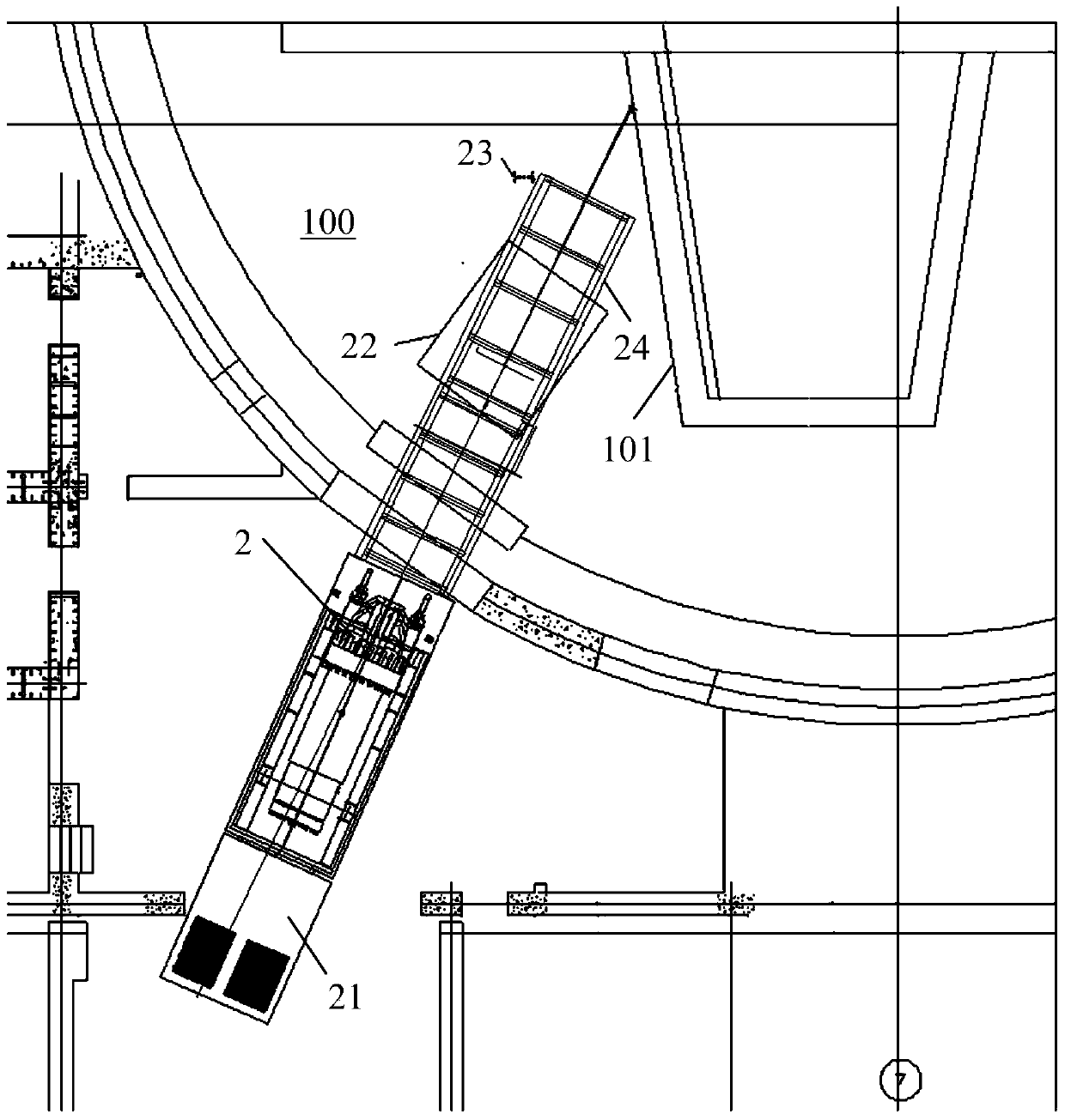
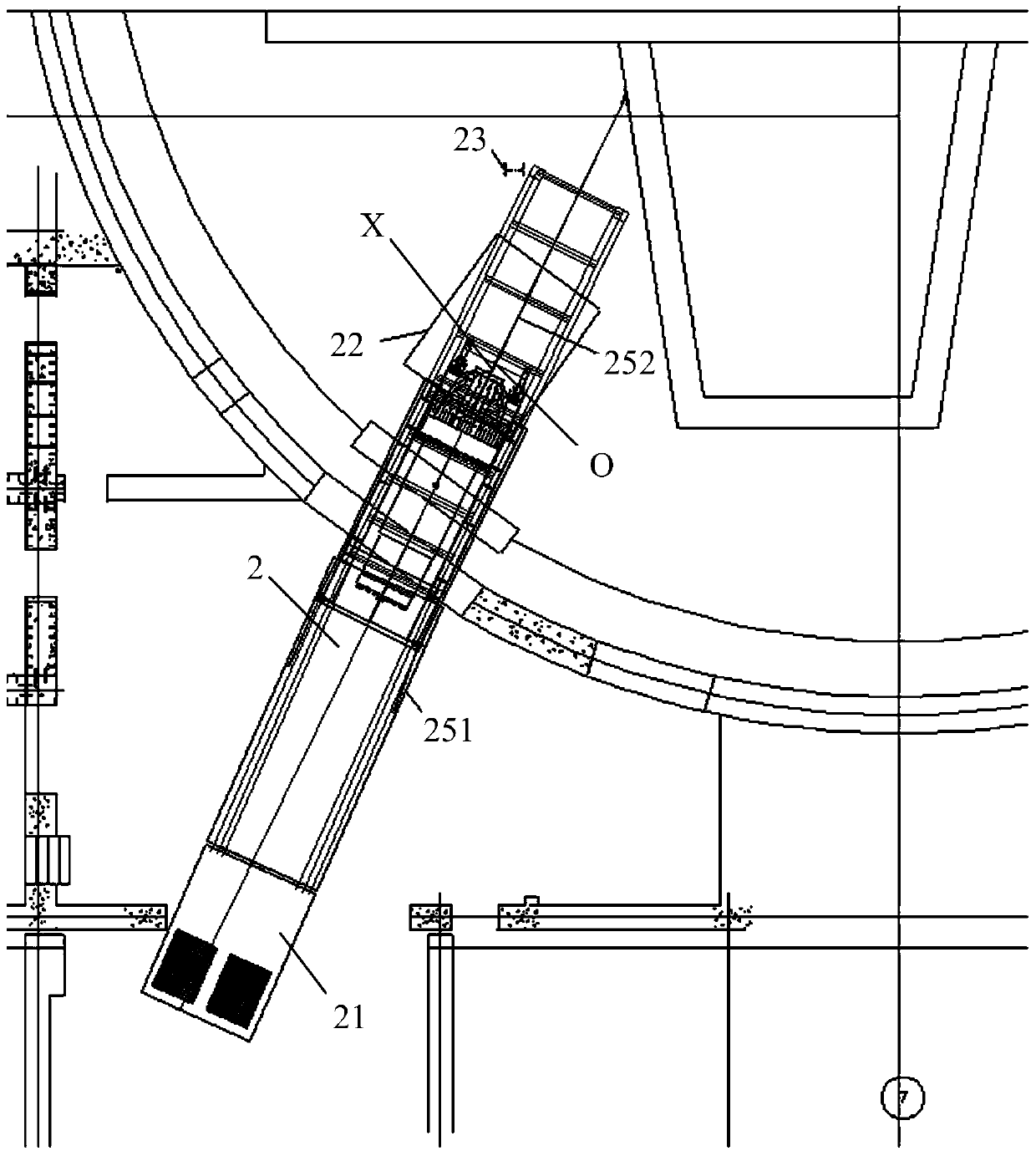
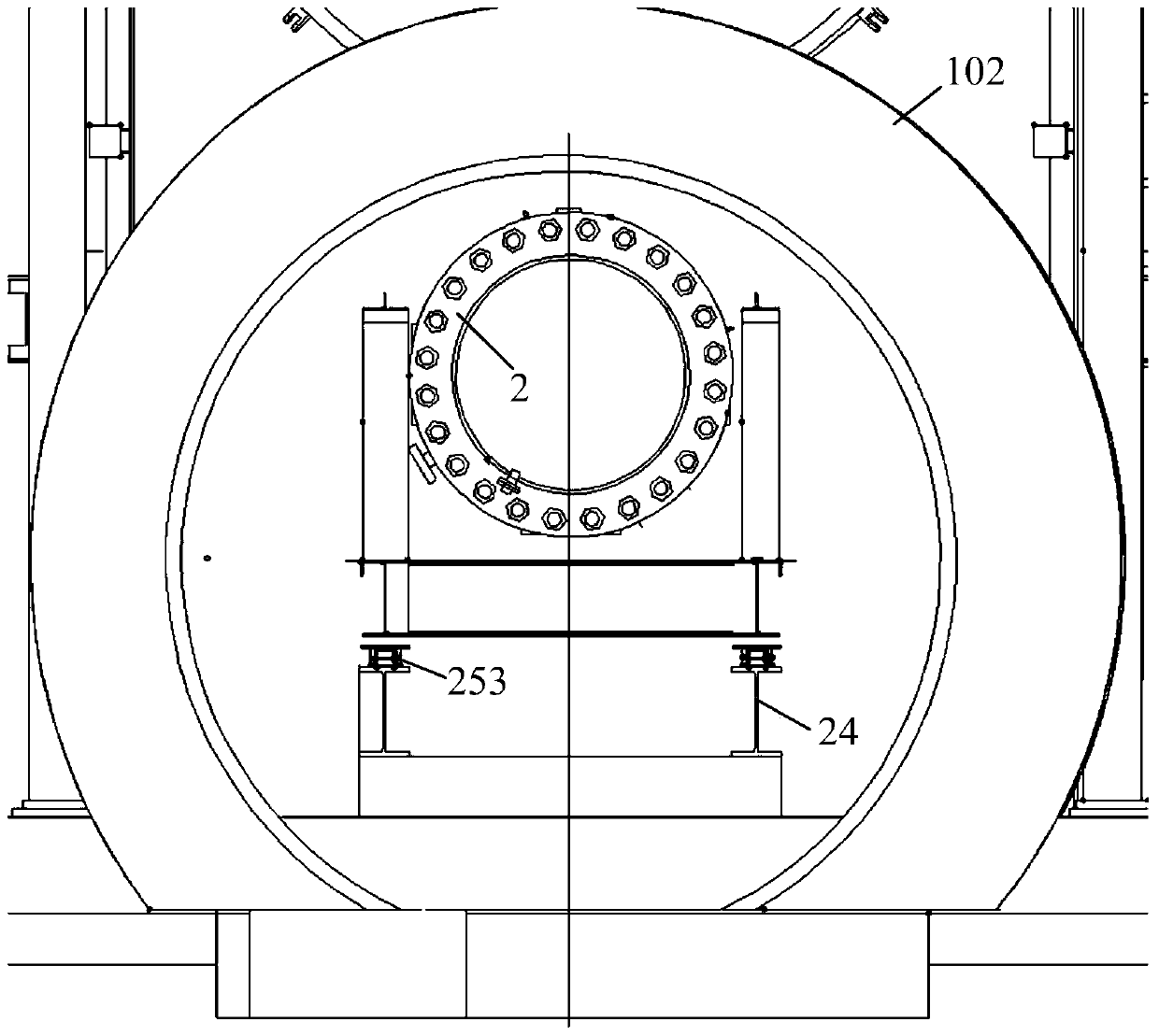
[0059] The present invention will be further described below in conjunction with specific embodiment and accompanying drawing, set forth more details in the following description so as to fully understand the present invention, but the present invention can obviously be implemented in many other ways different from this description, Those skilled in the art can make similar promotions and deductions based on actual application situations without violating the connotation of the present invention, so the content of this specific embodiment should not limit the protection scope of the present invention.

[0060] It should be noted that these and other subsequent drawings are only examples, which are not drawn according to the same scale, and should not be taken as limitations on the protection scope of the actual claims of the present invention.

[0061] In the following embodiments, the AP1000 nuclear power plant is taken as an example of the passive advanced PWR, but the presen...


PUM


Abstract

The invention relates to a passive advanced pressurized water reactor coolant pump installation technology. The passive advanced pressurized water reactor coolant pump installation technology is characterized in that a main pump occasional passage is provided; before a main pump is introduced to a nuclear island workshop, butt joint between a flat car transporting the main pump and the main pump occasional passage is completed; a draw gear is used to introduce a main pump / transport towing bracket assembly embarked on a mobile device to the nuclear island workshop; during the drawing process, a tail slipping device is used to prevent the moving speed becoming too fast, and then the main pump is moved to a turnover initial position; a ring crane hook is lifted and coordinates with moving of the mobile device so as to turnover the main pump, and at the same time, a tow rope of the tail slipping device is adjusted; the main pump is lifted to a steam generator cavity, and is located in a main pump installation mechanical device; a suction adapter in a pump housing completes the installation work before installation of the main pump; the main pump installation mechanical device is utilized to provide moving, positioning, adjusting and lifting of the main pump; and a sealing ring at the upper part of the main pump and the pump housing directly utilize the welded sealing technology to realize prevention of leakage during the operating process.

Description

technical field [0001] The invention relates to a method for installing a nuclear island reactor coolant pump. Background technique [0002] The method and installation method of introducing the main pump of the nuclear island of the existing nuclear power plant into the reactor building are as follows: [0003] 1. Installation of main pump casing support [0004] The support installation position of the main pump casing is mainly divided into vertical support and horizontal support. The vertical support is divided into upper base plate, outrigger, upper support and adjustment pad; the main structure of horizontal support is the damper. [0005] The vertical support is hoisted to the installation elevation by ring hoisting, the outriggers are connected to the upper base plate, the verticality of the outriggers is adjusted and the upper support is installed, and the elevation of the upper support is adjusted and positioned with the adjustment pad. [0006] After the welding...

Claims


Application Information

Patent Timeline
Patent Type & Authority Patents(China)
IPC IPC(8): G21D1/04G21C19/19
CPCG21C19/19G21D1/04Y02E30/00Y02E30/30
Inventor 刘鹏叶泉印苟锐甘锐陈赞科李建李仕杰董培科孔丽朵王泽锋蔡迎东
Owner CHINA NUCLEAR IND FIFTH CONSTR CO LTD
Why Eureka
Try Eureka