Lens device for surveillance camera

A camera and lens technology, which is applied in the field of lens devices for surveillance cameras, can solve the problems of single-sided blurred optical performance, bending of the main body of the lens barrel, and influence, and achieve the effects of reliable locking, easy locking operation, and easy locking operation

Active Publication Date: 2014-10-08
FUJIFILM CORP
View PDF7 Cites 5 Cited by
  • Summary
  • Abstract
  • Description
  • Claims
  • Application Information

AI Technical Summary

Problems solved by technology

[0004] However, in the method of locking the operation ring by pressing the front end of the knob against the outer peripheral surface of the lens barrel body in this way, since a concentrated load is applied to one point of the cylinder to compress it, when the rigidity of the lens barrel body is low When it is low, there are disadvantages such as bending of the lens barrel body and one-sided blurring that adversely affect optical performance

Method used


Image

  • Lens device for surveillance camera
  • Lens device for surveillance camera
  • Lens device for surveillance camera

Examples


Deformed example 1

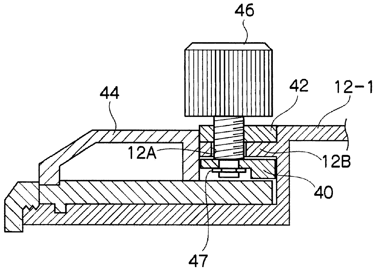
[0083] In this embodiment, a protrusion 12B is formed on the first lens barrel main body 12-1, and a hole 12A through which the locking knob 46 can penetrate is formed on the protrusion 12B. However, the first lens barrel main body 12- 1 is formed with a threaded hole for screwing the locking knob 46.

[0084] Picture 11 It is a modified example in which a threaded hole for screwing the lock knob 46 is formed in the first lens barrel main body 12-1' (fixed barrel). It should be noted that the same reference numerals are given to the same parts as in the present embodiment, and the description thereof will be omitted.

[0085] A screw hole 12D is formed in the protrusion 12B of the first lens barrel main body 12-1'. The screw direction of the screw hole 12D is opposite to the screw direction of the screw hole 42B. In this embodiment, a right-hand thread is applied to the threaded hole 42B, and therefore, the threaded hole 12D is a left-hand thread.

[0086] The lock knob 52 (lock ...

Deformed example 2

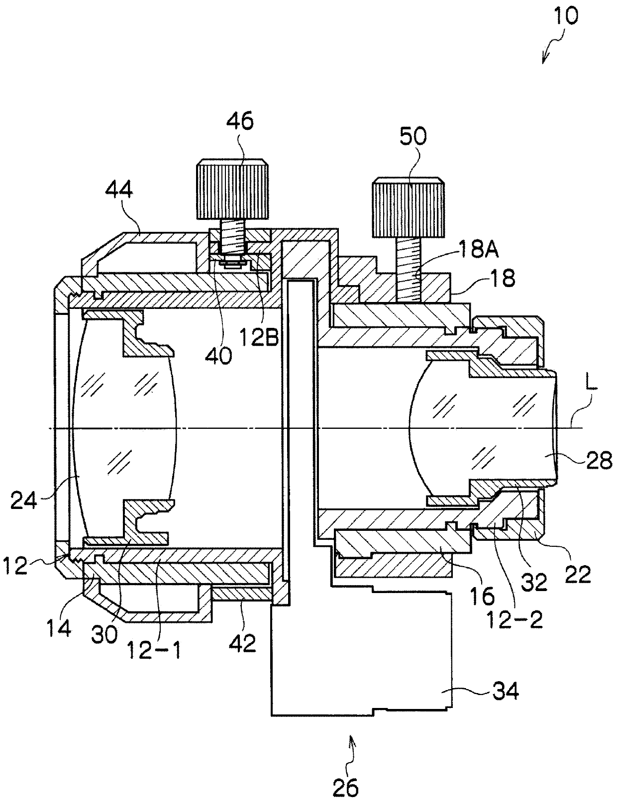
[0089] In this embodiment, the focus ring 14 is locked by making the brake member 40 and the brake ring 42 contact the focus ring 14 with their faces, respectively. However, even if the brake member 40 and the brake ring 42 do not face the focus ring 14. The abutment of the ring 14 can also lock the focus ring 14.

[0090] In addition, when the lock knob 46 is tightened too much and the brake member 40 is deformed and warped in the longitudinal direction due to changes in time, it is considered that the brake member 40 and the focus ring 14 may not face each other. It is the case where two lines (two points when viewed in the cross section) are in contact. In addition, when the brake ring 42 is formed of a material that hardly deforms, such as metal, it is considered that the brake ring 42 and the focus ring 14 are not in a plane but in a line (a point when viewed in a cross section). The contact situation.

[0091] Picture 12 It is a modified example in which the brake member ...


PUM


Abstract

Provided is a lens device for a surveillance camera, with which it is possible to securely lock an operating ring without deforming a lens-barrel, and with which the locking operation of the operating ring can be performed easily. When a locking knob (46) is rotated, screwing in the locking knob (46) into the focus ring (14), a brake member (40) which is integrated with the locking knob (46) moves towards a focus ring (14) and the entire inner peripheral surface of the brake member (40) comes into contact with the focus ring (14). At the same time, a brake ring (42) moves in the direction away from the brake member (40), and the inner periphery of the brake ring (42) touches the focus ring (14). In the way, when the locking knob (46) is screwed into the focus ring (14), the brake member (40) and the brake ring (42) sandwich the focus ring (14) from above and below, thereby locking (fixing in place) the focus ring (14).

Description

Technical field [0001] The present invention relates to a lens device for a surveillance camera, and more particularly, to a lens device for a surveillance camera having a locking mechanism in an operation ring for zooming and focusing. Background technique [0002] In a lens device for a surveillance camera that zooms and focuses manually (for example, a surveillance zoom lens), in order to prevent the set zoom position and focus position from moving, the zoom and focus operation ring A locking mechanism is provided. [0003] In the conventional locking mechanism of the operating ring, a knob screwed to the outer peripheral portion of the operating ring is screwed into the barrel main body to press the front end of the knob against the outer peripheral surface of the barrel main body. The operating ring is locked. [0004] However, in such a method of pressing the tip of the knob against the outer peripheral surface of the barrel body to lock the operating ring, since a concentrat...

Claims


Application Information

Patent Timeline
Patent Type & Authority Applications(China)
IPC IPC(8): G02B7/02G03B15/00H04N5/225
CPCG03B17/12G02B7/08
Inventor 合场大悟中村浩
Owner FUJIFILM CORP
Why Eureka
Try Eureka