
Mechanical burglarproof lock and matched keys thereof

A mechanical anti-theft lock and master key technology, applied in the direction of keys, locks with turning keys, building locks, etc., can solve the problem of low safety performance, achieve the effect of firm matching, avoid relative sliding, and facilitate unlocking

Inactive Publication Date: 2014-10-15
唐孝可
View PDF6 Cites 0 Cited by
  • Summary
  • Abstract
  • Description
  • Claims
  • Application Information

AI Technical Summary

Problems solved by technology

However, due to the relatively low safety performance of the existing tumbler locks, the keys can be prepared at will, so you can find key distributors everywhere in the market. Using the key mold of the tumbler lock, you can easily open the door within ten seconds with tin foil on it. no defense at all

Method used


Image

  • Mechanical burglarproof lock and matched keys thereof
  • Mechanical burglarproof lock and matched keys thereof
  • Mechanical burglarproof lock and matched keys thereof

Examples


Embodiment 1

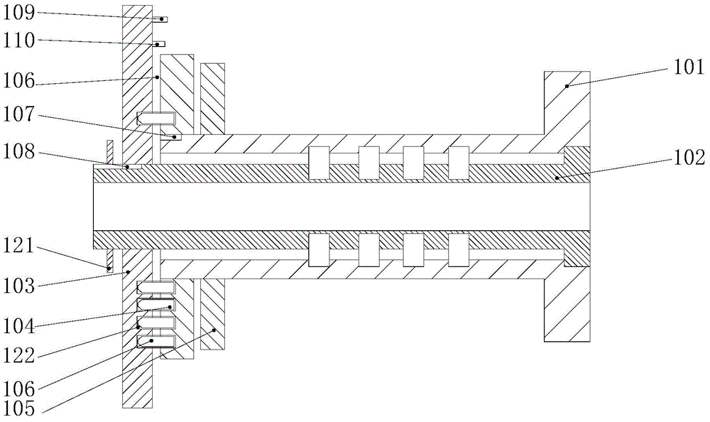
[0033] like Figure 1-8 As shown, a mechanical anti-theft lock is mainly composed of a main lock core 102 embedded in the lock main body 101 and having a length longer than the lock main body 101, and a secondary lock core 104 sleeved at the end of the lock main body 101. At the end of the main lock core 102 A disk 103 is set on the outside, and a plurality of groups of marbles 106 and springs connected with the marbles 106 are arranged between the disk 103 and the auxiliary lock cylinder 104, and the disk 103 corresponds to the auxiliary lock cylinder 104 Position is provided with pinball groove 122, and described pinball 106 and spring are all positioned in pinball groove 122, and limit hole 111 is set on disc 103 below described pinball 106, in order to drive deadbolt by rotating disc 103 119 movement realizes unlocking, is provided with pulling bar 109 on described disk 103, and described pulling bar 109 is connected with the connecting rod 116 that is connected on the dea...

Embodiment 2

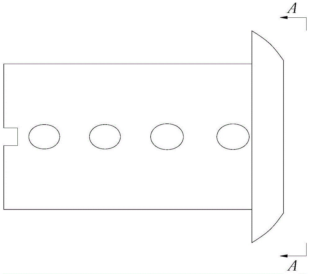
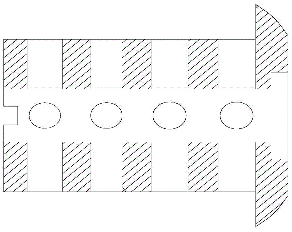
[0038] like Figure 9 and Figure 11-12 As shown, a key matched with the lock includes a main key 112 and a secondary key 113. The main key 112 matches the main lock cylinder 102 and is longer than the main lock cylinder 102. The main key 112 lifts the main lock cylinder 102 The pinball on the pin, the secondary key 113 is matched with the secondary lock core 104, the secondary key 113 is used to lift the marble 106 on the disc 103, and one end of the secondary key 113 is hinged with the end of the main key 112. After being inserted straight into the main lock cylinder 102, insert it to the bottom. At this time, the auxiliary key 113 is at a 90° angle to the main key 112 under the action of gravity. The end of the auxiliary key 113 away from the main key 112 is provided with a cylindrical pin that matches the clearance of the limit hole 111. 114, pull the main key 112 backward, turn the main key 112 to insert the cylindrical pin 114 on the auxiliary key 113 into the limit hol...


PUM


Abstract

The invention discloses a mechanical burglarproof lock and matched keys thereof. The mechanical burglarproof lock mainly comprises a main cylinder and an auxiliary cylinder, wherein the main cylinder is nested into a lock body and is longer than the same, the auxiliary cylinder sleeves the tail end of the lock body, a disc sleeves the tail end of the main cylinder, spring balls and springs connected with the spring balls are arranged between the disc and the auxiliary cylinder, the disc below the spring balls is provided with limit holes, and a lever is arranged on the disc and is connected with a connecting rod connected with a lock bolt. Via mutually perpendicular cylinders, only keys mutually perpendicular are capable of unlocking the lock, so that master keys or tinfoil are unable to unlock. The mutually perpendicular matched keys matched with the lock rotate the cylinders respectively to unlock, and during use, not only the keys need to bend by 90 degrees, but the spring balls jack up to certain positions and rotate, so the keys are hard to copy, and burglarproof performance of the lock is effectively improved.

Description

technical field [0001] The invention relates to a mechanical anti-theft lock and a key matched therewith. Background technique [0002] The existing tumbler lock uses a plurality of cylindrical parts with different heights to lock the lock cylinder. When the correct key is put in, each lock spring is pushed to the same height, and the lock cylinder is released to open. However, due to the relatively low safety performance of the existing tumbler locks, the keys can be prepared at will, so you can find key distributors everywhere in the market. Using the key mold of the tumbler lock, you can easily open the door within ten seconds with tin foil on it. Not fortified at all. Contents of the invention [0003] The object of the present invention is to provide a mechanical anti-theft lock and a key matching it, which can overcome the above-mentioned defects, adopt the design of two lock cylinders, the main lock cylinder and the auxiliary lock cylinder, and pass two mutually pe...

Claims


Application Information

Patent Timeline
IPC IPC(8): E05B15/14E05B27/04E05B35/12E05B19/08
Inventor 唐孝可
Owner 唐孝可
Learn More