Supercharge Your Innovation With Domain-Expert AI Agents!

A lever hand wheel

A handwheel and handle technology, which is applied in the field of machine tool parts, can solve the problems of the operator's effort and the torque is not long enough

Inactive Publication Date: 2016-06-15
STATE GRID CORP OF CHINA +1
View PDF5 Cites 0 Cited by
  • Summary
  • Abstract
  • Description
  • Claims
  • Application Information

AI Technical Summary

Problems solved by technology

[0002] Most of the existing handwheels are mostly circular handwheels, and a handle is installed on the circular handwheel. Such a handwheel is still very laborious for the operator, and the torque is not long enough.

Method used


Image

  • A lever hand wheel
  • A lever hand wheel
  • A lever hand wheel

Examples


Embodiment Construction

[0018] The principles and features of the present invention are described below in conjunction with the accompanying drawings, and the examples given are only used to explain the present invention, and are not intended to limit the scope of the present invention.

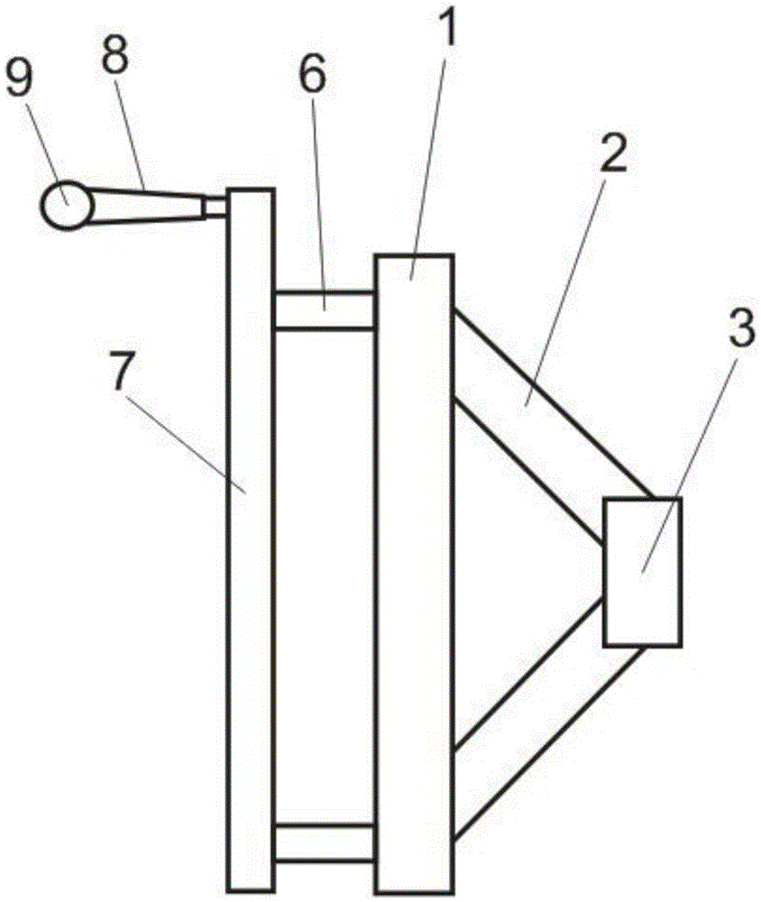
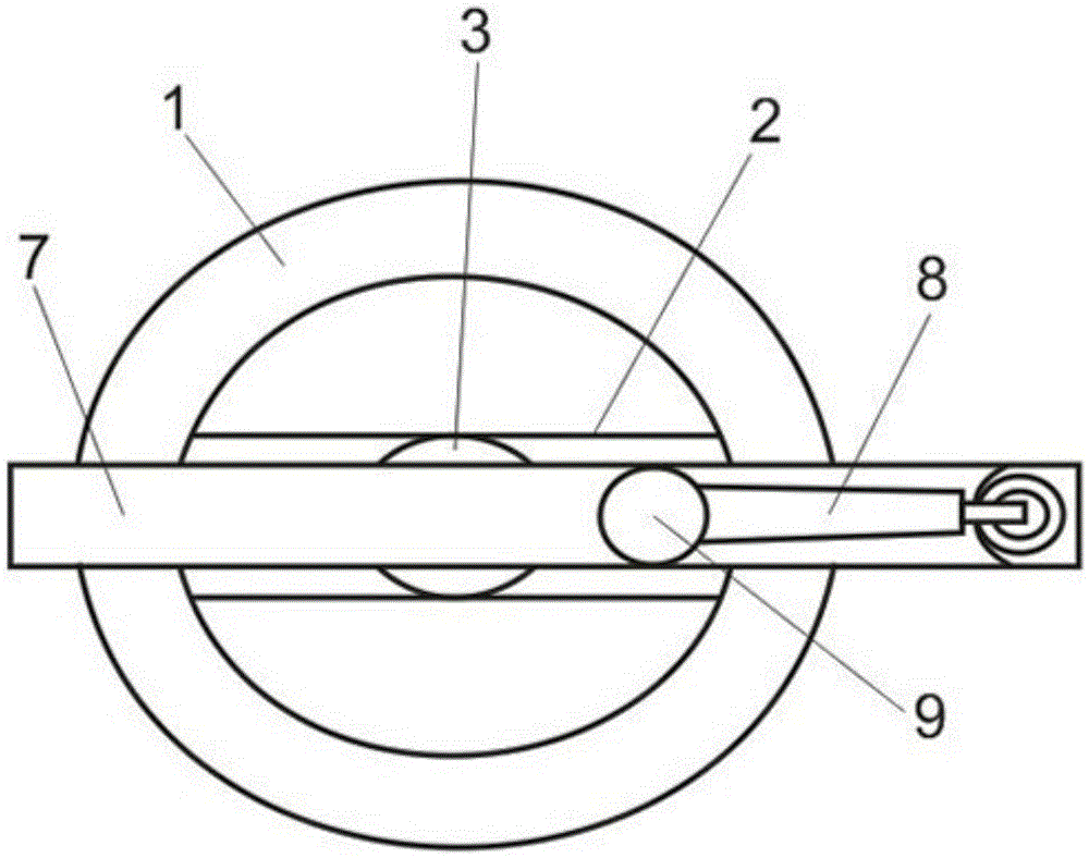
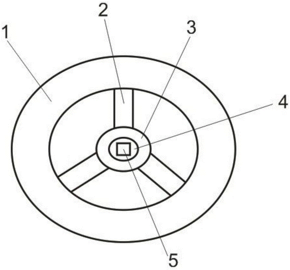
[0019] In a specific embodiment, such as figure 1 , figure 2 As shown, a force rod handwheel includes a circular body 1 and a force rod 7, one side of the circular body 1 is connected to a round core 3 through several spokes 2, and a wheel core 4 is arranged in the center of the round core 3 , the center of the wheel core 4 is provided with a wheel core hole 5; the circular body 1 and the force bar 7 are connected at both ends by connecting pieces 6 that are vertically connected to the two, and at one end of the force bar 7 A handle 8 is provided on a side away from the connecting member 6 , and the handle 8 is perpendicular to the force bar 7 .

[0020] The spokes 2 can be multiple, such as image 3 Shown is a ...


PUM


Abstract

The invention relates to a force bar handwheel, which comprises a circular body and a force bar. One side of the circular body is connected to a round core through several spokes. There is a wheel core hole; the circular body and the force rod are connected at both ends through connecting pieces vertically connected to the two, and a handle is provided on one end of the force rod away from the connecting piece, and The handle is perpendicular to the force bar. The invention increases the torque of the hand wheel and achieves the purpose of labor saving.

Description

technical field [0001] The invention relates to the technical field of machine tool components, in particular to a lever hand wheel. Background technique [0002] Most of the existing handwheels are mostly circular handwheels, and a handle is installed on the circular handwheel. Such a handwheel is still very laborious for the operator, and the torque is not long enough. Therefore, it is necessary to design a lever handwheel that can increase the torque of the handwheel, so as to increase the torque and achieve the purpose of labor saving. Contents of the invention [0003] The technical problem to be solved by the present invention is to provide a lever handwheel with increased torque and labor-saving. [0004] The technical solution of the present invention to solve the above-mentioned technical problems is as follows: a force bar handwheel, comprising a circular body and a force bar, one side of the circular body is connected to a circular core through several spokes, ...

Claims


Application Information

Patent Timeline
Patent Type & Authority Patents(China)
IPC IPC(8): G05G1/08
Inventor 于传维杨军狮
Owner STATE GRID CORP OF CHINA
Features
  • R&D
  • Intellectual Property
  • Life Sciences
  • Materials
  • Tech Scout
  • Unparalleled Data Quality
  • Higher Quality Content
  • 60% Fewer Hallucinations
Learn More