Reamer for implant surgery

一种扩孔钻、移植术的技术,应用在手术、植牙、牙修补术等方向,能够解决难以实现排出、切削效率低下、旋转干扰等问题,达到提高切除力和作业速度、提高切除力和作业性、降低摩擦阻抗的效果

Active Publication Date: 2014-10-15
安常勋
View PDF7 Cites 3 Cited by
  • Summary
  • Abstract
  • Description
  • Claims
  • Application Information

AI Technical Summary

Problems solved by technology

First, if figure 1 It shows that in the existing reaming drill, the cutting front end portion (110) with a sharp front end is formed eccentrically with the center axis of rotation (C) as the reference. Therefore, when the cutting portion (1) rotates, it is difficult to form C) True circle rotation centered
[0006] That is, when a rotational force is applied to the cutting part (1), a force that rotates around the cutting end part (110) with a sharp front end as an axis occurs, and a force that rotates about the center axis of rotation (C) of the cutting part (1) as a reference is generated. rotation interference, thus, it is difficult to form a true circle rotation
Therefore, using the figure 1 When the existing transplant reaming drill shown in the figure is operated, it needs to rotate at a low speed, and in order to ensure the true circle rotation of the cutting part (1), the center of rotation must first be formed before using the reaming drill, which causes the operation Inconvenience
[0007] Second, the existing reaming drills each have a cutting tip (110), a cutting edge (120), and an initial inclination angle (131), so the cutting efficiency is low
[0008] Third, the cutting efficiency is low, and the contact area between the reamer and the bone is large. Therefore, when the reamer rotates at high speed, the possibility of frictional heat is high, and there is bone necrosis due to frictional heat. Dangerous, therefore, it is not possible to perform surgery with high-speed rotation, but to perform low-speed rotation
[0009] Fourth, when the reamer is rotating, the saline that can cool the frictional heat between the reamer and the bone has a small passage to the working part, that is, the cutting part, so the cooling saline cannot reach the cutting part.
[0010] Fifth, the backlog space of the bone fragments generated by the rotation of the reamer is small, and it is difficult to realize the discharge by rotation. Therefore, in order to maintain the cutting efficiency of the effective cutting part, it is necessary to stop the operation and remove the bone fragments frequently

Method used


Image

  • Reamer for implant surgery
  • Reamer for implant surgery
  • Reamer for implant surgery

Examples


Embodiment Construction

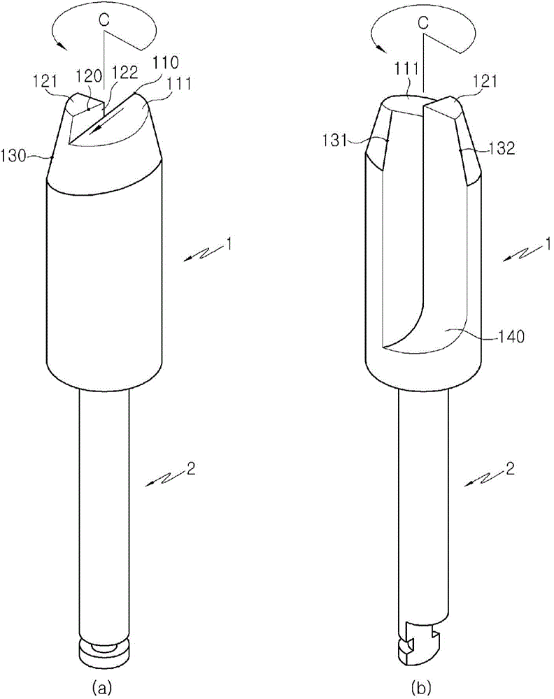
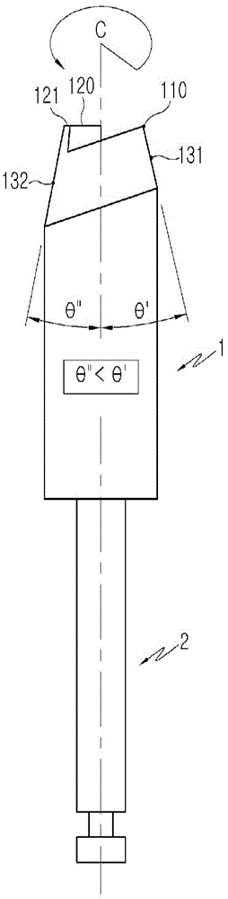
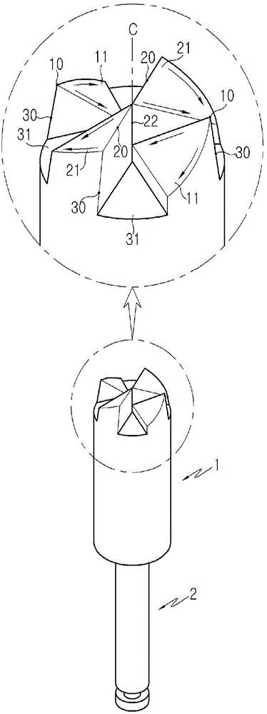
[0043] Below, the technical structure and effect of the preferred embodiment that can realize the purpose of the present invention will be described with reference to the accompanying drawings. The technical structure of the present invention has been patented in Korea by the applicant and inventor "An Changxun" who has utilized and improved the present invention After a part of the technical composition of "Cutting Lifting Reaming Drill for Maxillary Sinus Transplantation (Korean Patent No. 10-0792649)", a new structure was added to achieve more advanced effects than before. figure 1 , 2 A conventional reamer for transplantation (Korean Patent No. 10-0792649) shown in .

[0044] figure 1 , 2 It is the existing cross-sectional view and front view of the reamer used for transplantation equivalent to Korean Patent No. 10-0792649, such as figure 1 , as shown in 2, the existing transplant reamer, as a cutting and lifting reamer for transplantation, includes: in order to form a ...


PUM


Abstract

The present invention relates to a reamer for forming a hole in the bone for implant placement which is specifically structured so that cutting edges (20), which have a linear form that is horizontal to cutting front end portions (10) having a front end, are alternately and radially formed at an upper portion of a cutting portion (1), wherein the rear side of the cutting front end portions (10) is formed as a depressed surface (11) which slants downward toward the rotation central axis (C) of the cutting portion (1), wherein the rear side of the cutting edges (20) is formed as a slanted surface (21) which slants downward toward an outer circumferential surface of the cutting portion (1), wherein bone storage grooves (31), in which residue of the bone (40) that is eliminated is inserted and accumulated, are formed between the cutting front end portions (10) and the cutting edges (20); which are alternately formed, and an incline angle of side surface slanted edges (30), which are formed on an outer circumference of the cutting front end portions (10) and the cutting edges (20), becomes gradually smaller in the direction of rotation.

Description

technical field [0001] The present invention relates to a reamer for forming a hole in a bone for transplantation, and more particularly relates to a reamer for transplantation which not only facilitates selection of a position for hole processing, but also, The efficiency of bone resection is improved, thus, high-speed rotation is possible, and frictional resistance can be reduced during high-speed rotation, thereby improving the operability for transplantation. Background technique [0002] figure 1 is a cross-sectional view of an existing reamer used for transplantation, figure 2 Front view of an existing reamer used for grafting. refer to figure 1 , 2 , the existing reamer for transplantation, as a cutting and lifting reamer for transplantation, includes the following composition: a protruding surface (121), in order to form a stepped edge (122), so that the upper end of the cutting part (1) One side including the outer periphery of the front face is raised upward;...

Claims


Application Information

Patent Timeline
Patent Type & Authority Applications(China)
IPC IPC(8): A61C3/02A61B17/16A61C8/00
CPCA61B17/1615A61B17/1688A61B17/1673A61C8/0089A61C8/0092A61B17/16A61C3/02A61C8/00
Inventor 安常勋
Owner 安常勋
Why Eureka
Try Eureka