Steerable underreaming bottom hole assembly and method

a bottom hole and assembly technology, applied in the direction of drilling pipes, directional drilling, borehole/well accessories, etc., can solve the problems of inaccurate azimuth of the curved borehole formed while sliding, difficult to accurately predict the build rate when sliding, and poor steerability of the bottom hole assembly

Inactive Publication Date: 2005-02-01
HALLIBURTON ENERGY SERVICES INC
View PDF10 Cites 72 Cited by
  • Summary
  • Abstract
  • Description
  • Claims
  • Application Information

AI Technical Summary

Benefits of technology

A significant advantage of the present invention is that the bottom hole assembly does not require specially made components. Instead, each of the components of the bottom hole assembly may be selected by the operator as desired to achie...

Problems solved by technology

When reamers are used in a conventional steerable bottom hole assembly immediately above the bit and below the motor housing, the bottom hole assembly has very poor steerability.
More particularly, it is difficult to accurately predict the build rate when sliding, regardless of the positioning of stabilizers above the reamer.
Because of high vibration, the azimuth of the curved borehole formed while sliding may be inaccurate.
Moreover, borehole quality is generally poor due to high vibration, which prohibits the motor housing from “holding steady” in the well.
Because of the disadvantages of a ste...

Method used


Image

  • Steerable underreaming bottom hole assembly and method
  • Steerable underreaming bottom hole assembly and method
  • Steerable underreaming bottom hole assembly and method

Examples


Embodiment Construction

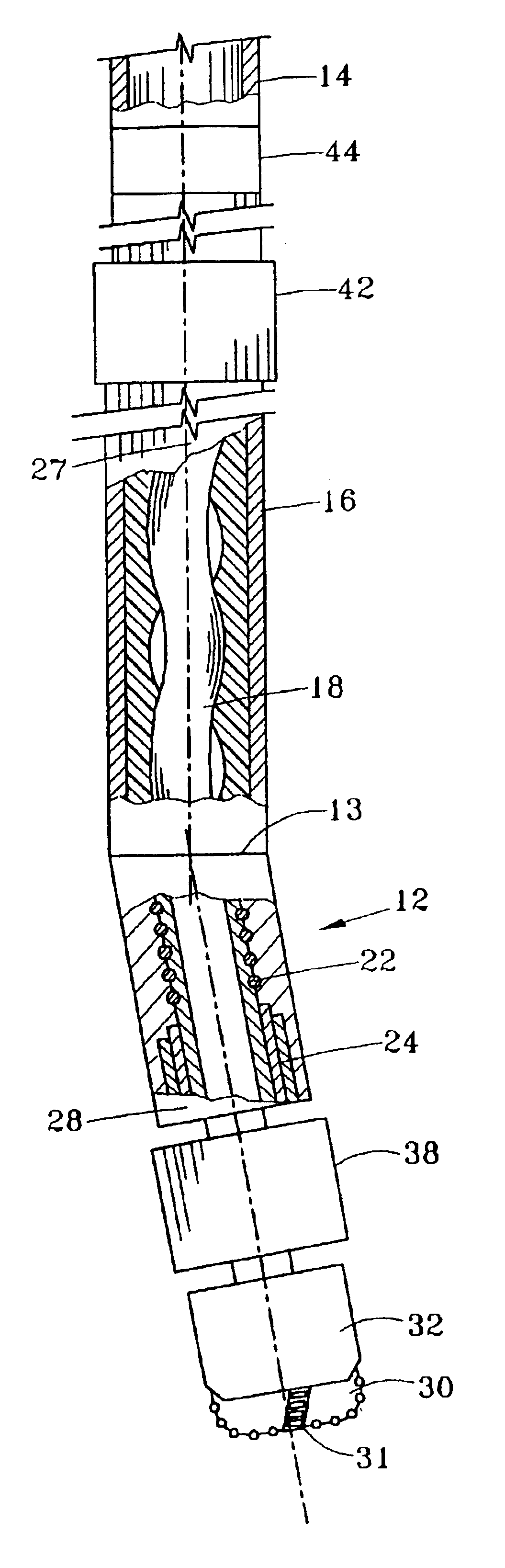
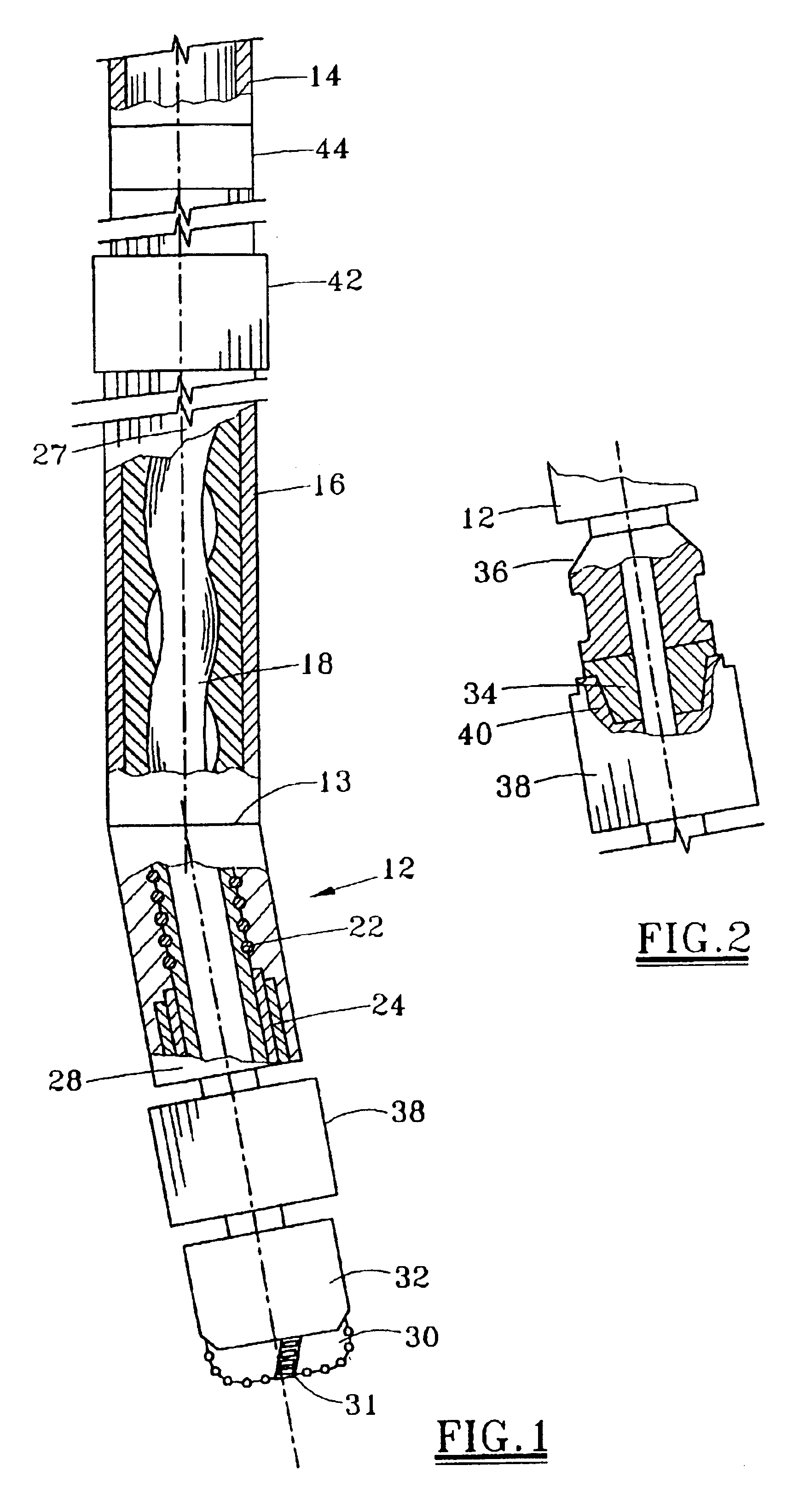
Steerable drilling systems conventionally utilize a downhole motor (mud motor) powered by drilling fluid (mud) pumped from the surface to rotate the bit. The motor rotates the bit using a drive section, with the rotor output from the drive section extending through a bent sub or bent housing to rotate the bit. The bent sub may actually comprise more than one bend to obtain a net effect which is referred to as the “bend angle” of the bottom hole assembly. The downhole motor which utilizes a lobed rotor is referred to as a positive displacement motor (PDM).

FIG. 1 depicts a steerable bottom hole assembly (BHA) for drilling both a curved section and a straight section of the borehole. The BHA includes a PDM 12 which is conventionally suspended in the well from a tubular string 14, which is conventionally threaded drill pipe. PDM 12 includes a motor housing 16 with a substantially cylindrical outer surface and a conventional lobed rotor 18 within the power section of the motor for rotati...


PUM


Abstract

A steerable bottom hole assembly may be used for drilling both a curved section and straight section of the borehole, with the bottom hole assembly including a reamer beneath the downhole motor 12. The bottom hole assembly includes a bit 30 having a bit face defining a bit diameter, and a gauge section 32 having a substantially uniform diameter cylindrical surface approximating the bit diameter and having an axially length of at least 75% of the bit diameter. The motor is preferably run slick without stabilizers for engaging the wall of the borehole.

Description

FIELD OF THE INVENTIONThe present invention relates to steerable bottom hole assemblies when used for underreaming or enlarging a section of a wellbore.BACKGROUND OF THE INVENTIONSteerable bottom hole assemblies include a positive displacement motor (PDM) or “mud motor” which has a bend angle that allows a drilling operator to build at a desired rate when “sliding” the non-rotating motor housing. The bend angle of the bent sub or bent motor housing, in combination with the contact points of the bottom hole assembly (BHA) with the well bore wall, thus largely determines the build rate for drilling the curved borehole section. When the drill string and the motor housing are rotated, the drilling operator drills a straight or tangent section of the borehole. The rate of penetration (ROP) of the bit drilling through the formation is frequently significantly less when “sliding” to build rather than rotating the bottom hole assembly from the surface to drill the straight borehole sections...

Claims


Application Information

Patent Timeline
IPC IPC(8): E21B17/02E21B7/04E21B7/06E21B17/03E21B7/08
CPCE21B17/03E21B7/067
Inventor CHEN, CHEN-KANG D.SMITH, JR., WILLIAM H.
Owner HALLIBURTON ENERGY SERVICES INC
Why Eureka
Try Eureka