Expandable reamers for earth-boring applications and methods of using the same

a technology of earth-bore drilling and expandable reamers, which is applied in the direction of fluid removal, drilling machines and methods, and well accessories, etc., can solve the problems of difficulty in removal from the borehole, the tendency of conventional bi-center and eccentric bits to wobble and deviate from the path intended for the borehole, and the disadvantage of narrowing the borehol

Active Publication Date: 2008-06-05
BAKER HUGHES INC
View PDF48 Cites 73 Cited by
  • Summary
  • Abstract
  • Description
  • Claims
  • Application Information

AI Technical Summary

Benefits of technology

[0009]In some embodiments, the present invention includes expandable reamer tools comprising an outer body, a fluid passageway extending through the outer body, and at least one blade configured to move relative to the outer body between a retracted position and an expanded position in a direction oriented at an acute angle of less than ninety degrees (90°) to a longitudinal axis of the outer body. Optionally, the tool may further comprise a moveable inner sleeve member configured to move from a first position to a second position in response to a predetermined hydraulic pressure differential created between portions of the fluid passageway. In the first position, the moveable inner sleeve member may prevent hydraulic pressure within the fluid passageway from acting on the at least one blade. In the second position, the moveable inner sleeve member may allow hydraulic pressure within the fluid passageway to act directly on the at least one blade.

Problems solved by technology

While adding additional casing allows a borehole to reach greater depths, it has the disadvantage of narrowing the borehole.
Furthermore, conventional bi-center and eccentric bits may have the tendency to wobble and deviate from the path intended for the borehole.
Conventional expandable reaming assemblies, while more stable than bi-center and eccentric bits, may be subject to damage when passing through a smaller diameter borehole or casing section, may be prematurely actuated, and may present difficulties in removal from the borehole after actuation.

Method used


Image

  • Expandable reamers for earth-boring applications and methods of using the same
  • Expandable reamers for earth-boring applications and methods of using the same
  • Expandable reamers for earth-boring applications and methods of using the same

Examples


Embodiment Construction

[0034]The illustrations presented herein are, in some instances, not actual views of any particular reamer tool, cutting element, or other feature of a reamer tool, but are merely idealized representations that are employed to describe the present invention. Additionally, elements common between figures may retain the same numerical designation.

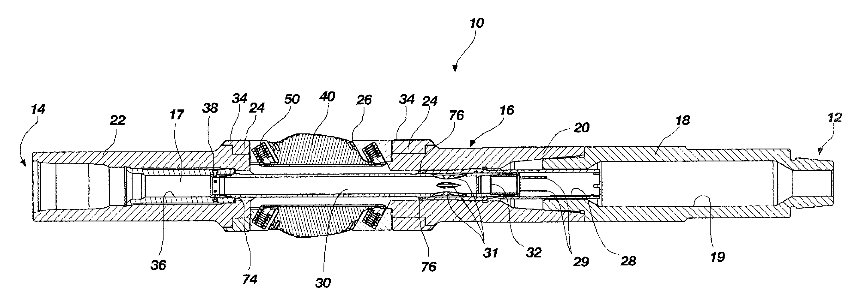
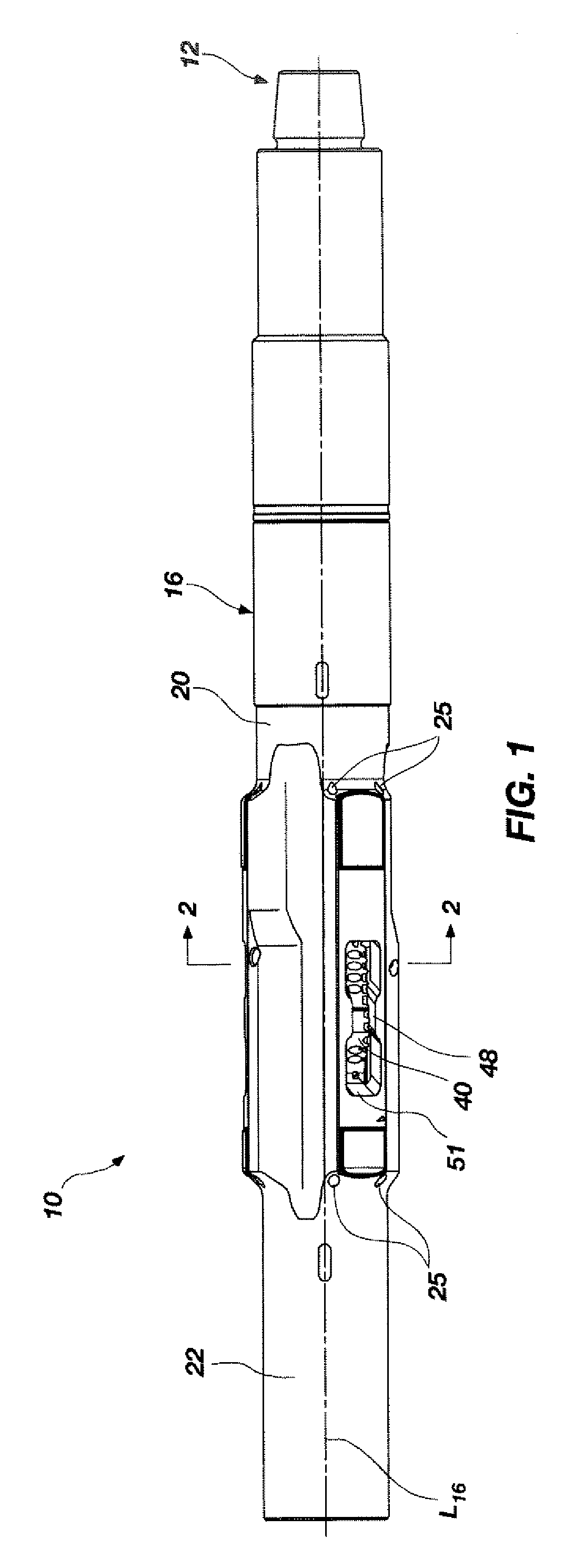
[0035]An expandable reamer tool 10 according to an embodiment of the present invention is shown in FIG. 1. The expandable reamer tool 10 may include a generally cylindrical outer body 16 having a longitudinal axis L16. The outer body 16 of the expandable reamer tool 10 may have a first lower end 12 and a second upper end 14. The terms “lower” and “upper,” as used herein with reference to the ends 12, 14, refer to the typical positions of the ends 12, 14 relative to one another when the expandable reamer tool 10 is positioned within a well bore. The lower end 12 of the outer body 16 of the expandable reamer tool 10 may include a set of threads...


PUM


Abstract

Expandable reamer tools include an outer body, a fluid passageway extending through the outer body, and at least one blade configured to slide relative to the outer body between a retracted position and an expanded position in a direction oriented at an acute angle of less than ninety degrees (90°) to a longitudinal axis of the outer body. In some embodiments, the tools may include a moveable inner sleeve member configured to selectively allow hydraulic fluid pressure within the fluid passageway to act directly on the at least one blade. Methods for enlarging a borehole using such expandable reamer tools and methods for removing such expandable reamer tools from a borehole are also disclosed.

Description

CROSS-REFERENCE TO RELATED APPLICATION[0001]This application claims the benefit of U.S. Provisional Patent Application Ser. No. 60 / 872,745, filed Dec. 4, 2006, the disclosure of which is incorporated herein in its entirety.FIELD OF THE INVENTION[0002]The present invention relates generally to drilling of subterranean well bores. More particularly, the present invention relates to expandable reamer tools and methods of using such tools to enlarge a subterranean well bore. The expandable reamer tools may comprise a tubular body configured with expandable blades that may be positioned in a first retracted position and then displaced radially outward and upward to a second expanded position.BACKGROUND[0003]In drilling oil, gas, and geothermal wells, casing is conventionally installed and cemented to prevent the well walls from caving into the subterranean borehole. Casing is also conventionally installed to isolate different formations, to prevent crossflow of formation fluids, and to e...

Claims


Application Information

Patent Timeline
Patent Type & Authority Applications(United States)
IPC IPC(8): E21B7/28
CPCE21B10/322
Inventor RADFORD, STEVEN R.SHU, SCOTT S.SHALE, LES T.MORRIS, MARK E.KIZZIAR, MARK R.ZAHRADNIK, ANTON F.
Owner BAKER HUGHES INC
Why Eureka
Try Eureka