Torque converter

a technology of torque converter and clutch chamber, which is applied in the direction of rotary clutches, fluid couplings, gearings, etc., can solve the problems of difficult to ensure the pressure receiving area for obtaining a predetermined engagement, and achieve the effect of preventing centrifugal hydraulic pressure, enhancing the circularity of oil in the clutch chamber, and improving the efficiency of lubricating and cooling

Inactive Publication Date: 2005-06-23
SUBARU CORP
View PDF7 Cites 64 Cited by
  • Summary
  • Abstract
  • Description
  • Claims
  • Application Information

AI Technical Summary

Benefits of technology

[0020] Further, according to the present invention, the empty space can be ensured in the outer periphery of the drum portion by downsizing the lockup clutch and accommodating it in the front cover having the inner disc portion, the drum portion, and the outer disc portion.
[0021] In addition, since the lubricating oil passage communicating with the clutch chamber and the lockup oil passage communicating with the engagement oil chamber are formed inside the main shaft, the hydraulic pressures supplied to the respective oil chambers can be individually set. Further, it is possible to prevent a centrifugal hydraulic pressure from being generated in the engagement oil chamber due to the lubricating oil within the clutch chamber.
[0022] Furthermore, since the orifice is provided in the partition wall sectioning the clutch chamber and the converter chamber, it is possible to enhance circularity of the oil in the clutch chamber and improve efficiency of lubricating and cooling the inside of the clutch chamber.
[0023] Additionally, since the two lubricating oil passages communicate with each other independently in the clutch chamber, it is possible to enhance the circularity of the oil in the clutch chamber and improve efficiency of lubricating and cooling the inside of the clutch chamber.
[0024] And, since the member for forming the partition wall and the outer disc portion and the member for forming the inner disc portion and the drum portion are welded to form the front cover, the portion of the front cover and the lockup clutch are modularized so as to form the external mounting structure. Therefore, the outward protruding amount of the torque converter can be easily changed.
[0025] Since the electric motor having the rotor linked by the engine output shaft is arranged outside the drum portion, it is possible to achieve the downsizing of the power transmission apparatus including the torque converter and the electric motor.

Problems solved by technology

However, if a lockup piston is downsized, it becomes difficult to ensure a pressure receiving area for obtaining a predetermined engagement force.

Method used


Image

  • Torque converter
  • Torque converter
  • Torque converter

Examples


first embodiment

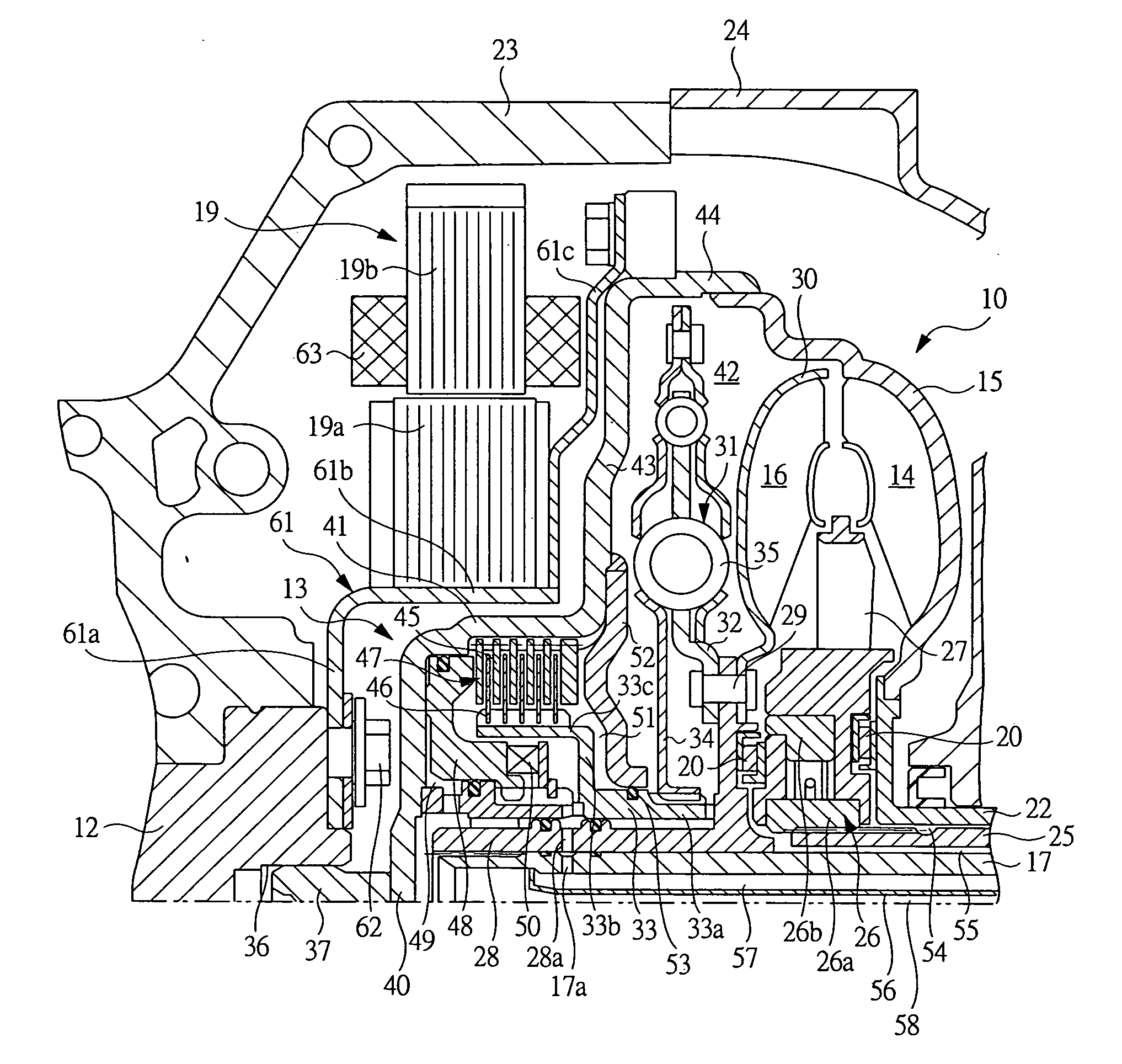
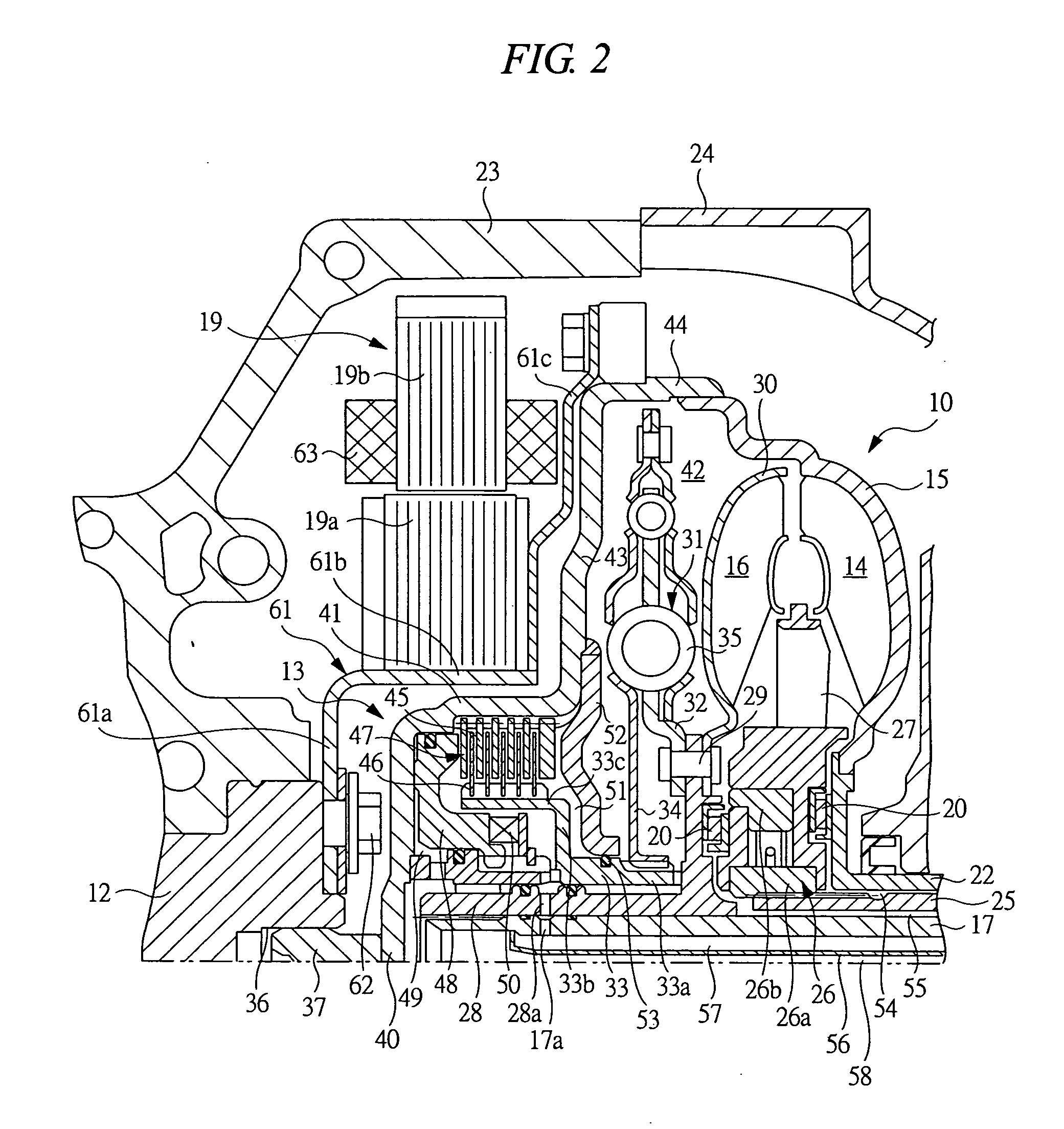
[0035]FIG. 2 is an enlarged sectional view of a main portion of a torque converter 10 according to the present invention. As shown in FIG. 2, a motor housing 23 pivotally supporting the engine output shaft 12 and accommodating the power generating motor 19 is assembled in a converter housing 24 pivotally supporting the main shaft 17 and accommodating the torque converter 10. A stator shaft 25 arranged between the main shaft 17 and the impeller hub 22 is fixed to the converter housing 24, and an inner race 26a of a one-way clutch 26 is spline-connected to the stator shaft 25, and a stator 27 is arranged in an outer race 26b of the one-way clutch 26.

[0036] A hollow turbine hub 28 is spline-connected to an outer periphery of an end of the main shaft 17, and the turbine hub 28 rotates integrally with the main shaft 17. A runner shell 30 of the turbine runner 16 and a spring seat 32 of a lockup damper 31 are linked to a flange portion of the turbine hub 28 by a rivet 29. Thrust bearings ...

second embodiment

[0049]FIG. 3 is an enlarged sectional view of a main portion of the torque converter according to the present invention. The same member as those shown in FIG. 2 is denoted by the same reference numerals. As shown in FIG. 3, an orifice 64 having a micro diameter and communicating with the clutch chamber 51 and the converter chamber 42 is formed in the partition wall 52 separating the clutch chamber 51 from the converter chamber 42. Since the orifice 64 as well as the lubricating oil passage 57 communicates with the above-mentioned chambers, it is possible to enhance the circularity of the oil in the clutch chamber 51 and to efficiently lubricate and cool the inside of the clutch chamber 51. Since the oil flowing through the orifice 64 is depressurized, it does not influence the engagement hydraulic pressure of the lockup clutch 47.

third embodiment

[0050]FIG. 4 is an enlarged sectional view of the main portion of the torque converter according to the present invention. The same member as those shown in FIG. 2 is denoted by the same reference numeral. As shown in FIG. 4, another flow passage forming member 65 is assembled outside the flow passage forming member 56 so that one end thereof is fixed to the inner peripheral surface of the main shaft 17 and extends axially. The lubricating oil passage 57 is formed so as to be divided into a first lubricating oil passage 57a and a second lubricating oil passage 57b. The first lubricating oil passage 57a communicates with the inside of the drum portion 33c in the clutch chamber 51 via the communication holes 17a and 28a, and the second lubricating oil passage 57b communicates with the outside of the drum portion 33c in the clutch chamber 51 via the communication holes 17b and 28b. As mentioned above, the two lubricating oil passages 57a and 57b are provided in the main shaft 17 so as ...


PUM


Abstract

A torque converter which can prevent an engagement pressure of a lockup clutch from becoming very high. A converter chamber is formed between an outer disc portion of a front cover and an impeller shell. A partition wall separating a clutch chamber and a converter chamber is provided in the outer disc portion. A clutch chamber has a drive plate serving as an input side of an engine output, a driven plate serving as an output side, and a lockup piston forming an engagement oil chamber along with an inner disc portion of the front cover. Since the partition wall is provided, the lockup clutch can be engaged without being affected by the hydraulic pressure within the converter chamber.

Description

BACKGROUND OF THE INVENTION [0001] The present invention relates to a torque converter to which a hydraulically actuated lockup clutch is attached. [0002] The torque converter includes an impeller shell which is mounted to a front cover linked to an engine output shaft and is provided with a pump impeller, and a turbine runner connected to a main shaft so as to be opposed to the pump impeller, and serves as a power transmission apparatus amplifying an engine output and transmitting thereof to the main shaft serving as an output shaft of the torque converter. Since the torque converter transmits the engine output by using fluid, i.e., oil as a medium, a power transmission loss caused by a slip of the fluid is unavoidable. Accordingly, in a range in which a rotational speed difference between the pump impeller and the turbine runner is small, the engine output shaft and the main shaft are set in a directly coupled state by actuating the lockup clutch so that the engine output is direc...

Claims


Application Information

Patent Timeline
Patent Type & Authority Applications(United States)
IPC IPC(8): F16H41/24F16H41/28F16H41/30F16H45/02
CPCB60K6/387B60K6/405B60K6/48F16H45/02Y02T10/6221F16H2045/0226F16H2045/0231F16H2045/0247F16H2045/0284F16H2045/021Y02T10/62
Inventor MASUYA, KOUICHI
Owner SUBARU CORP
Why Eureka
Try Eureka