Brake apparatus

a technology of brake pedal and pedal, which is applied in the direction of brake system, brake components, vehicle components, etc., can solve the problems of deterioration of pedal feeling and change in pedal pressure required to depress the brake pedal, and achieve the effect of improving pedal feeling

Inactive Publication Date: 2008-09-25
HITACHI LTD
View PDF11 Cites 37 Cited by
  • Summary
  • Abstract
  • Description
  • Claims
  • Application Information

AI Technical Summary

Benefits of technology

[0004]The present invention has been contrived in consideration of the above-mentioned problem in the conventional art, and an object of the invention is to provide a brake apparatus in which a hydraulic pressure in a master cylinder is prevented from being increasingly varied while an anti-lock brake system is in operation, whereby a pedal feeling can be improved.

Problems solved by technology

In a case that such an electric booster is used in combination with an anti-lock brake system, a problem arises in that a hydraulic pressure in a master cylinder undergoes a change during operation of the anti-lock brake system, and the change in the hydraulic pressure is transmitted to an input member (primary piston) where it becomes a reactive force acting against a brake pedal, thereby causing a change in a pedal pressure required to depress the brake pedal.
As a result, during operation of the anti-lock brake system, a pedal pressure is subject to increasing variation, which causes a pronounced deterioration in pedal feeling.

Method used


Image

  • Brake apparatus
  • Brake apparatus
  • Brake apparatus

Examples


Embodiment Construction

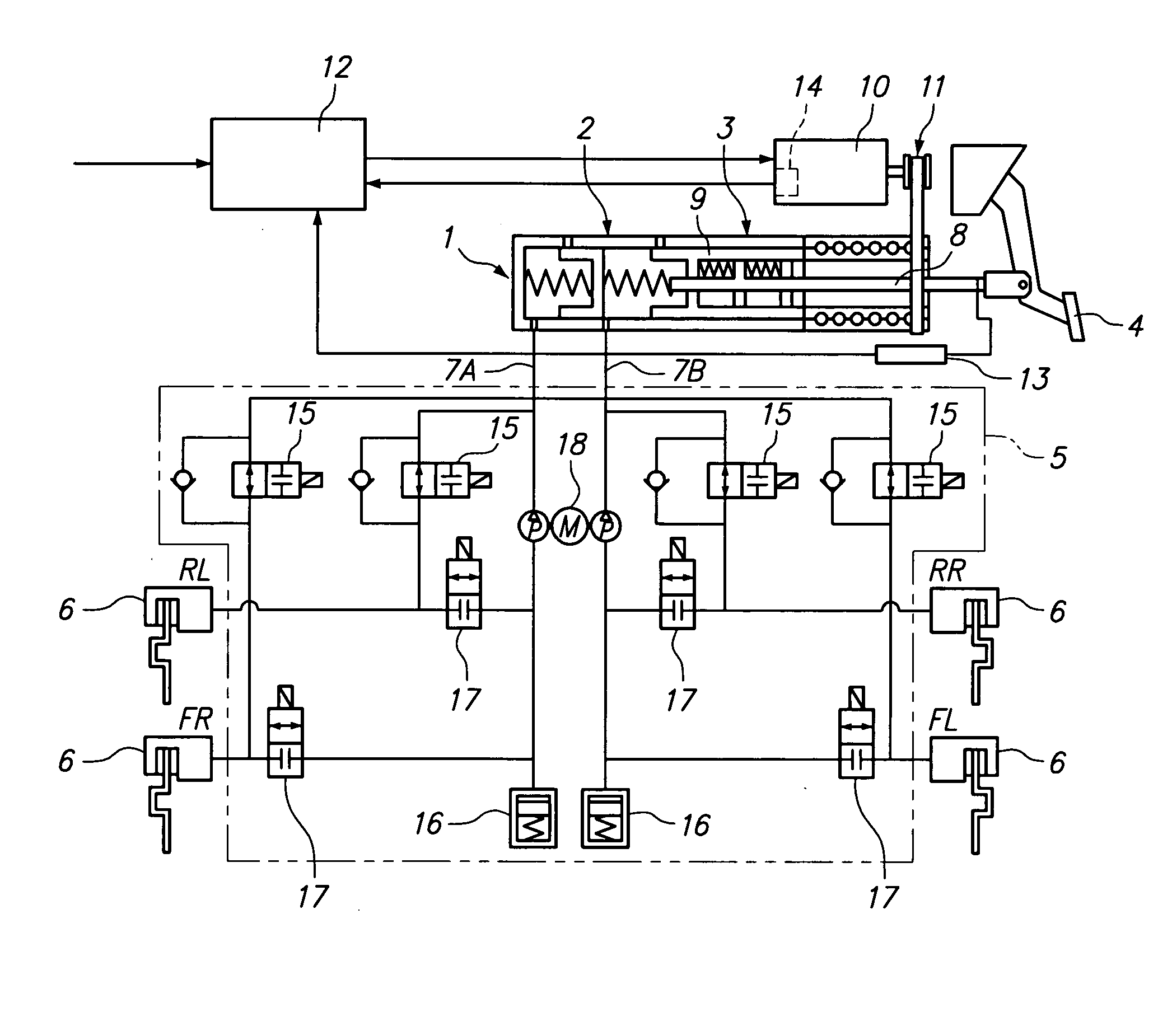
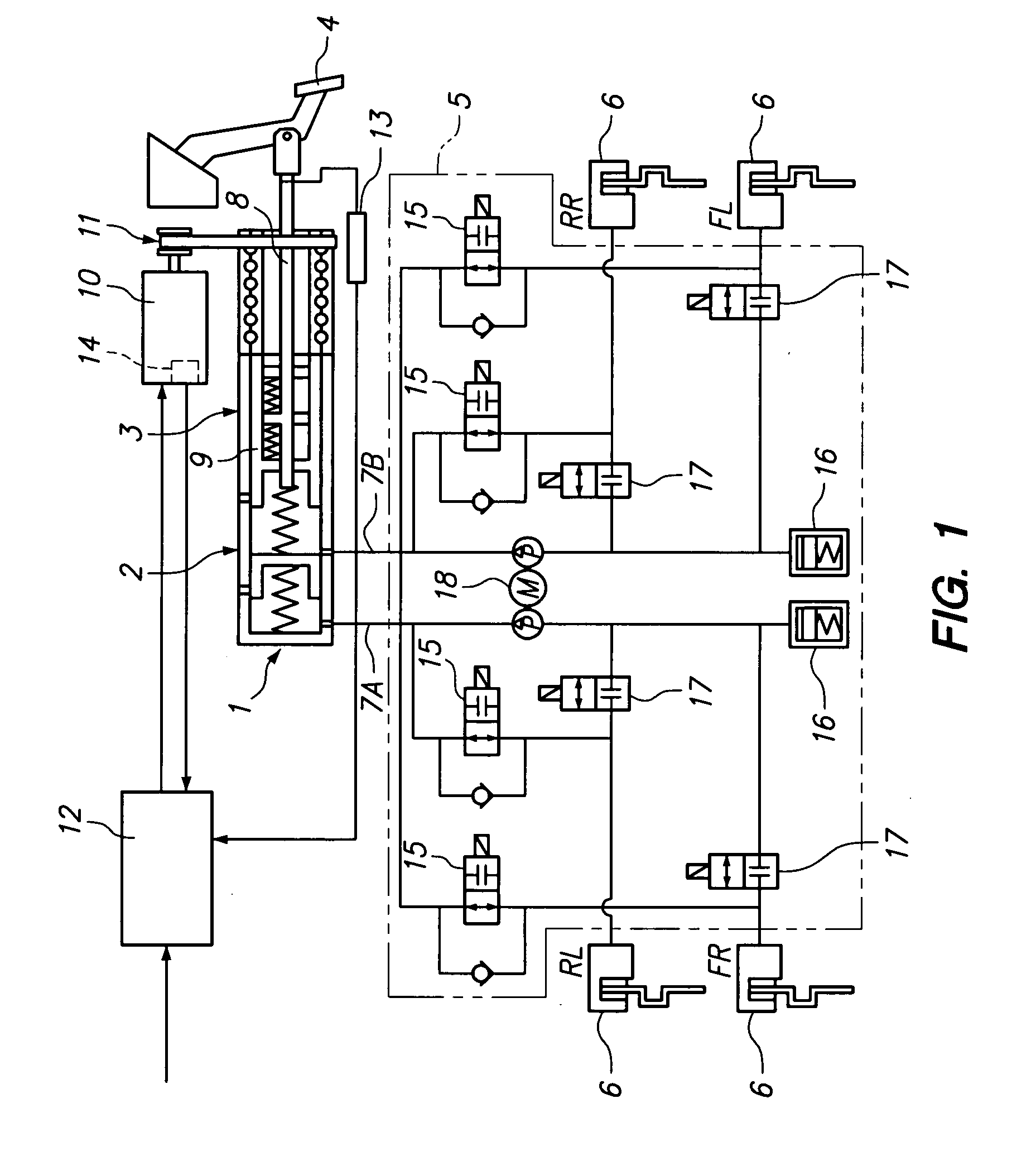
[0015]Hereinafter, preferred embodiments of the present invention will be described with reference to the accompanying drawings. FIG. 1 illustrates a structure of an entire system of a brake apparatus according to the present invention. In FIG. 1, reference numeral 1 denotes a hydraulic unit comprising a tandem master cylinder 2 and an electric booster 3 which are integrally provided. The hydraulic unit 1 generates a brake hydraulic pressure in the master cylinder 2 in response to an operation of a brake pedal 4. Reference numeral 5 denotes a hydraulic circuit for an anti-lock brake system (ABS). Reference numeral 6 denotes a wheel cylinder, which serves as a disk brake in the illustrated embodiment. The wheel cylinders 6 are connected such that, in the illustrated embodiment, a X-type circuit arrangement is formed, i.e., RL makes a pair with FR and RR makes a pair with FL, and the wheel cylinders 6 are connected through the ABS hydraulic circuit 5 to primary brake fluid passages 7A...


PUM


Abstract

An object of the present invention is to provide a brake apparatus in which a hydraulic pressure in a master cylinder is prevented from being increasingly varied while an anti-lock brake system is in operation, and therefore a pedal feeling can be improved. The brake apparatus comprises an electric booster including an input member which moves forward or backward in response to an operation of a brake pedal, an assist member which moves forward or backward by being driven by an electric actuator using an electric motor as its driving source. The electric booster generates a boosted brake hydraulic pressure in the master cylinder under an input thrust provided to the input member through the brake pedal and an assist thrust provided to the assist member by the electric actuator. In the brake apparatus, the brake hydraulic pressure generated in the master cylinder is supplied to a wheel cylinder through a hydraulic pressure circuit of an anti-lock brake system, and, while the anti-lock brake system in operation, an operation of the assist member is restricted by a booster control, whereby a change in a hydraulic pressure in the master cylinder due to the operation of the assist member can be restrained.

Description

BACKGROUND OF THE INVENTION[0001]The present invention relates to a brake apparatus for use in braking a vehicle, and more particularly, the present invention relates to a brake apparatus provided with an electric booster which is operated by use of an electric actuator as a boosting source.[0002]Examples of an electric booster which is operated by use of an electric actuator as a boosting source include an electric booster disclosed in Japanese Patent Application Publication H10-138909. This electric booster comprises a primary piston (input member) which moves forward or backward in response to an operation of a brake pedal, and a booster piston (assist member) which moves forward or backward by being driven by an electric machinery (electric actuator). This electric booster generates a brake hydraulic pressure in a master cylinder under an input thrust transmitted through the brake pedal to the primary piston and a booster thrust (assist thrust) transmitted by the electric machin...

Claims


Application Information

Patent Timeline
Patent Type & Authority Applications(United States)
IPC IPC(8): B60T13/128
CPCB60T8/3265B60T13/745B60T8/447B60T8/4275
Inventor YAMADA, YUKIHIKOYAMAGUCHI, TOHMAOBATA, TAKUYAOIKAWA, HIROTAKA
Owner HITACHI LTD
Why Eureka
Try Eureka