Master Cylinder And Brake System Using The Same

a technology of master cylinder and brake system, which is applied in the direction of fluid braking transmission, brake system, vehicle components, etc., can solve the problems of unstable up-and-down movement of floating valve body, and achieve the effect of stable and reliable opening and closing, simple structure and improved durability of valve body

Inactive Publication Date: 2009-08-06
BOSCH CORP
View PDF4 Cites 5 Cited by
  • Summary
  • Abstract
  • Description
  • Claims
  • Application Information

AI Technical Summary

Benefits of technology

[0015]According to the master cylinder pertaining to the present invention that is configured in this manner, the flow rate control valve that controls the flow of the hydraulic fluid between the reservoir and the hydraulic chamber is disposed with the valve body whose one end portion is rotatably supported, so by causing the valve body to rotate using the one end portion as a fulcrum, the valve body can be stably and reliably caused to open and close, and the flow rate control valve can be configured by a simple structure. Moreover, the valve body is simply caused to rotate in response to the flow of the hydraulic fluid, so the durability of the valve body can be improved.
[0016]Further, during the start of operation of the master cylinder, the hydraulic fluid tries to escape from the hydraulic chamber of the master cylinder to the reservoir, but the flow rate control valve closes in response to the flow of that hydraulic fluid and restricts the flow of the hydraulic fluid that escapes from the hydraulic chamber of the master cylinder to the reservoir, so during the start of operation of the master cylinder, the amount of the hydraulic fluid that escapes to the reservoir can be reduced, and the dead stroke of the piston of the master cylinder can be reduced.
[0017]Moreover, when the master cylinder supplies the hydraulic fluid to the external device, the hydraulic fluid tries to flow from the reservoir of the master cylinder to the hydraulic chamber, but the flow rate control valve opens in response to the flow of that hydraulic fluid and does not restrict the flow of the hydraulic fluid that is taken in from the reservoir of the master cylinder through the hydraulic chamber, so a sufficient amount of the hydraulic fluid can be reliably supplied to the external device, and excellent self-support performance of the hydraulic fluid of the master cylinder can be obtained.
[0018]Moreover, the fluid passage with the small flow path area that is formed when the flow rate control valve closes is configured by the notch that is formed in the reservoir or the cylinder body or by the small hole that is formed in the valve body, so the flow rate restrictive control of the flow rate control valve can be performed by a simple structure, and the operational reliability of the flow rate control valve can be further improved.
[0019]In particular, according to the brake system pertaining to the present invention, during the start of operation of the master cylinder, the dead stroke of the piston of the master cylinder can be reduced, so the dead stroke of the brake pedal can be reduced and the pedal feeling can be improved.
[0020]Further, when automatic braking is caused to operate as a result of the brake fluid intake means being operated such that the brake fluid is taken in from the reservoir through the hydraulic chamber of the master cylinder and supplied to the brake cylinder, excellent self-support performance of the hydraulic fluid of the master cylinder can be obtained, so automatic braking can be reliably caused to operate.

Problems solved by technology

For this reason, the up-and-down movement of the floating valve body is not stable, and consideration of the stability and reliability of the opening-and-closing operation of the floating valve body becomes necessary.

Method used


Image

  • Master Cylinder And Brake System Using The Same
  • Master Cylinder And Brake System Using The Same
  • Master Cylinder And Brake System Using The Same

Examples


Embodiment Construction

[0024]Below, the best modes for implementing the present invention will be described using the drawings.

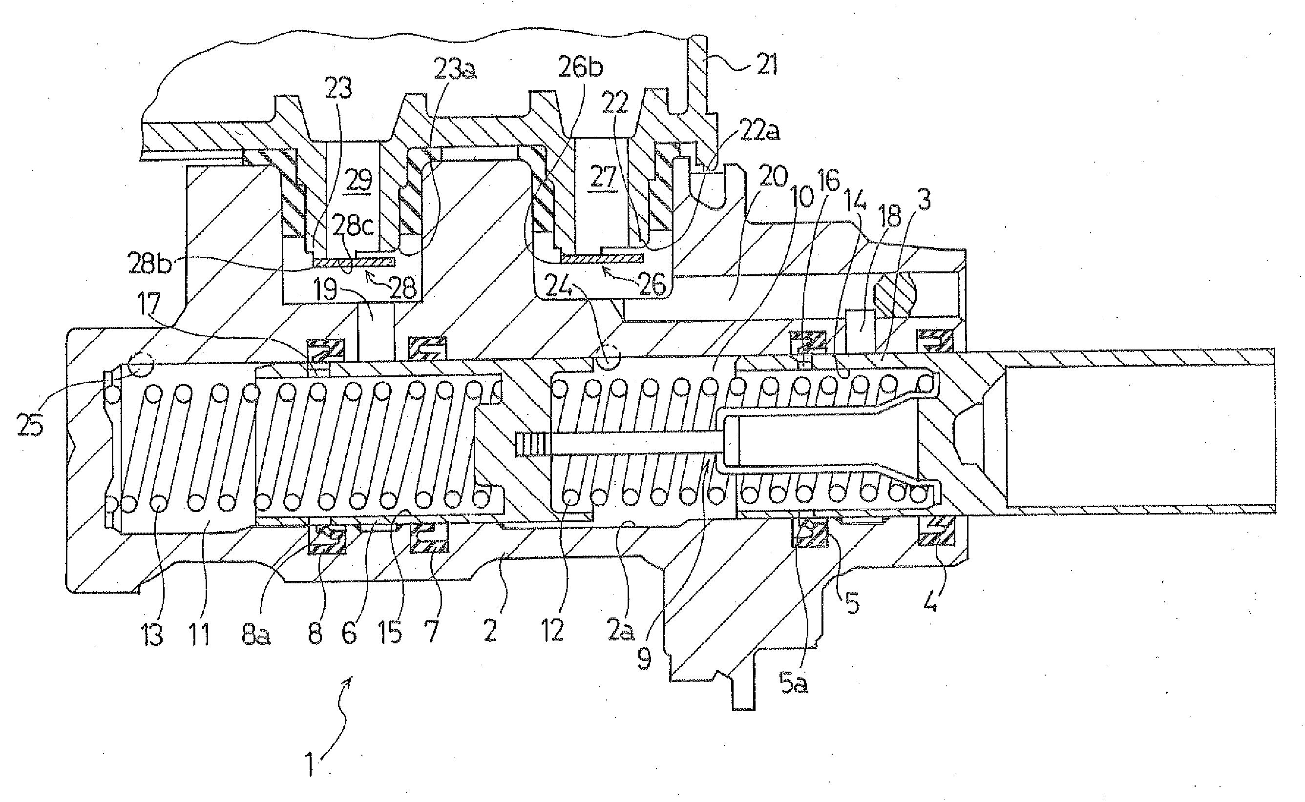
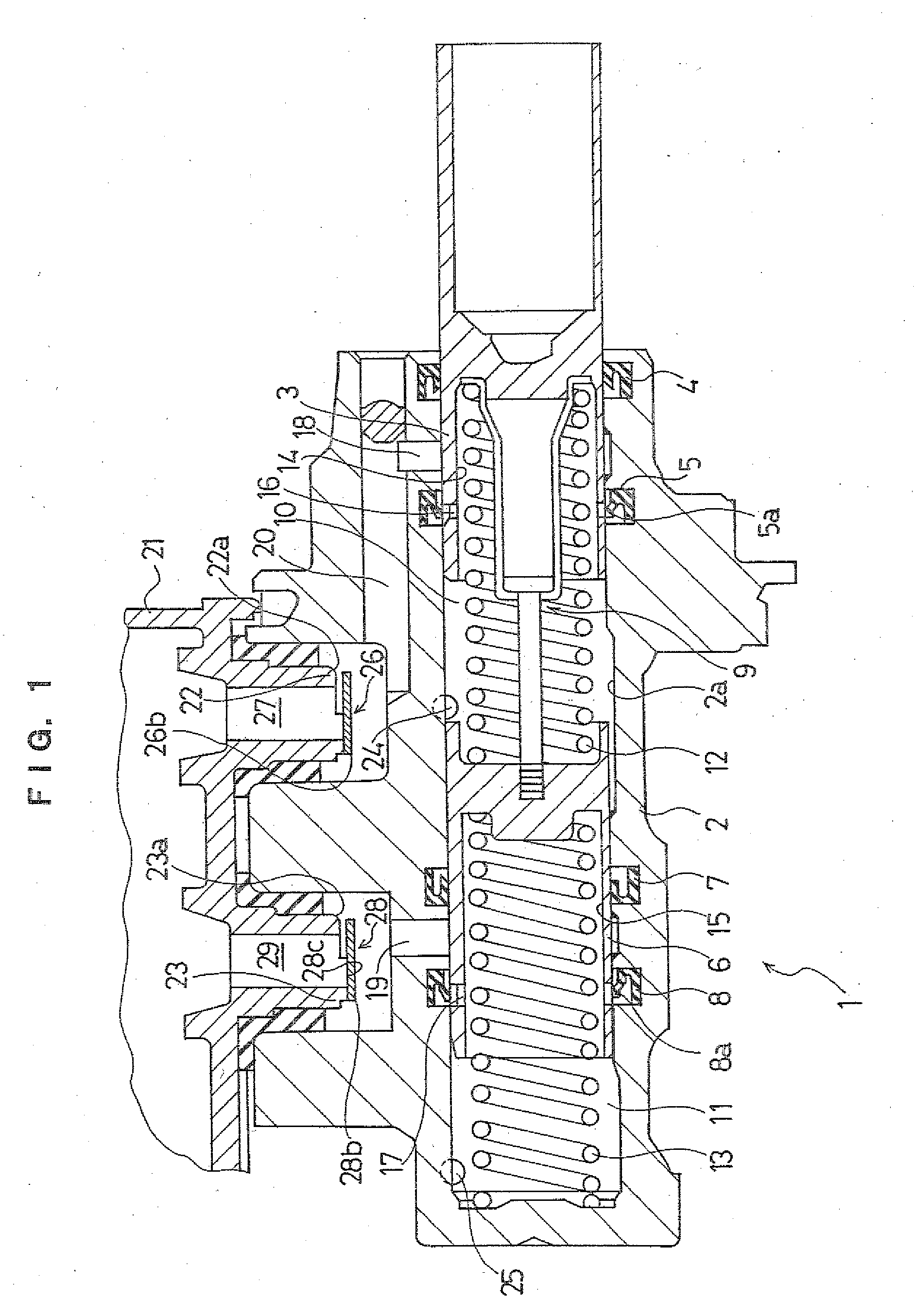
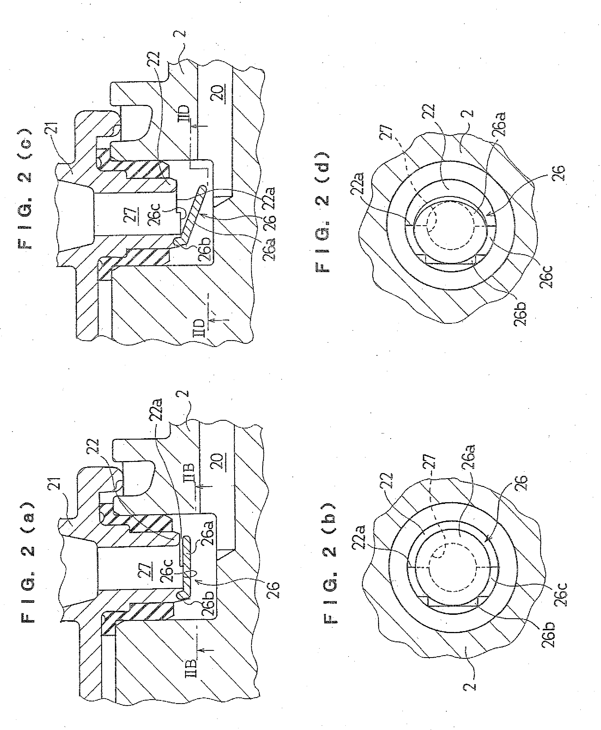
[0025]FIG. 1 is a longitudinal sectional diagram schematically showing an example of an embodiment of a master cylinder pertaining to the present invention, and FIG. 2 shows a first connecting opening portion of a reservoir of the example shown in FIG. 1, with (a) being a partially enlarged diagram of FIG. 1 showing a non-operating state of a valve, (b) being a cross-sectional diagram along line IIB-IIB in (a), (c) being the same diagram as (a) showing an operating state of the valve, and (d) being a cross-sectional diagram along line IID-IID in (c). In the following description, front and rear correspond respectively to left and right in FIG. 1.

[0026]As shown in FIG. 1, a master cylinder 1 of this example is configured as a tandem master cylinder, and this master cylinder 1 includes a cylinder body 2. A primary piston 3 is fitted into an axial hole 2a in this cylinder body 2 so a...


PUM


Abstract

A master cylinder of the present invention is disposed with valve bodies (26a) and (28a). Support portions (26b) and (28b) on one end side of these valve bodies (26a) and (28a) are respectively supported in connecting opening portions (22) and (23) of a reservoir (21) so as to be rotatable using these support portions (26b) and (28b) as fulcrums. During the start of operation, when brake fluid flows out from hydraulic chambers (10) and (11) to the reservoir (21), the valve bodies (26a) and (28a) rotate and close such that the flow of the brake fluid is restricted by notches (22a) and (23a), and the dead strokes of pistons (5) and (6) become small. During intake of the brake fluid by pumps; when the brake fluid flows from the reservoir (21) to the hydraulic chambers (10) and (11), the valve bodies (26a) and (28a) rotate and open such that the brake fluid flows to the hydraulic chambers (10) and (11) without its flow being restricted, and fluid self-support performance is ensured.

Description

BACKGROUND ART[0001]The present invention relates to the technical field of a master cylinder and a brake system using the same that includes a reservoir that stores hydraulic fluid and which, during normal operation, is capable of cutting of f a hydraulic chamber from this reservoir to generate hydraulic pressure and, during non-operation, is capable of taking in hydraulic fluid inside the reservoir through the hydraulic chamber by a pump, and particularly relates to the technical field of a master cylinder and a brake system that ensure a necessary intake amount of hydraulic fluid during intake of hydraulic fluid inside a reservoir by pumps to make the self-support performance of hydraulic fluid excellent and reduce the dead stroke of a master cylinder piston during normal operation.[0002]Conventionally, in brake systems of vehicles such as automobiles, there have been proposed brake systems where, during normal braking operation, braking operates as a result of braking liquid pre...

Claims


Application Information

Patent Timeline
Patent Type & Authority Applications(United States)
IPC IPC(8): B60T11/28
CPCB60T11/20B60T11/28B60T11/232
Inventor TAIRA, KAZUHISA
Owner BOSCH CORP
Why Eureka
Try Eureka