Master cylinder comprising means for injecting brake fluid into said master cylinder, and braking system comprising such a master cylinder

a master cylinder and brake fluid technology, applied in the field of braking system, can solve the problems of increasing complexity and increasing fragility, and achieve the effect of high robustness and simple production

Active Publication Date: 2014-05-20
ROBERT BOSCH GMBH
View PDF7 Cites 2 Cited by
  • Summary
  • Abstract
  • Description
  • Claims
  • Application Information

AI Technical Summary

Benefits of technology

[0004]It is an object of the present invention to offer a braking system that uses a master cylinder allowing decoupling between the brake pedal and the pressure obtaining in the braking circuit supplied by said master cylinder that is highly robust and very simple to produce.
[0005]Another object of the present invention is to offer a braking system that has a brake pedal that is particularly pleasant for the driver to use, that is to say that has a refined pedal feel.

Problems solved by technology

At the expense of increased complexity and increased fragility, devices incorporating a simulator allow decoupling between the position of a brake pedal and the hydraulic pressure available in the braking circuits.

Method used


Image

  • Master cylinder comprising means for injecting brake fluid into said master cylinder, and braking system comprising such a master cylinder
  • Master cylinder comprising means for injecting brake fluid into said master cylinder, and braking system comprising such a master cylinder
  • Master cylinder comprising means for injecting brake fluid into said master cylinder, and braking system comprising such a master cylinder

Examples


Embodiment Construction

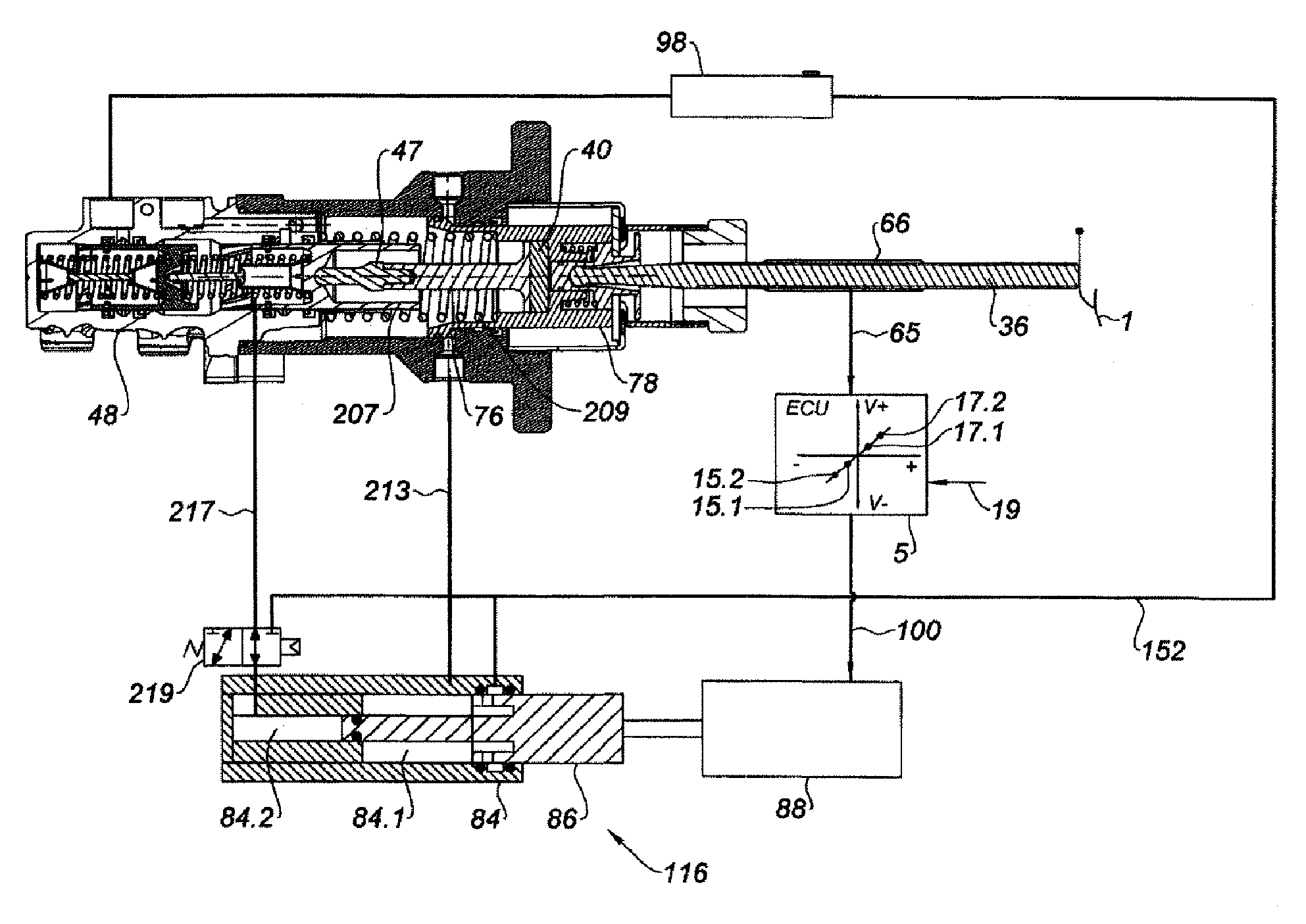
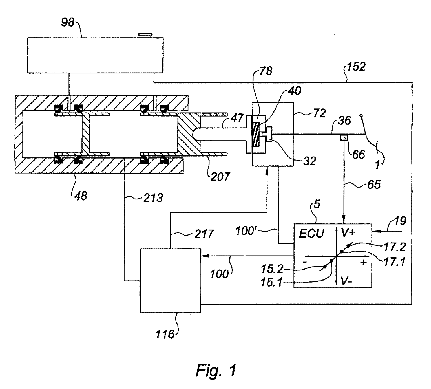
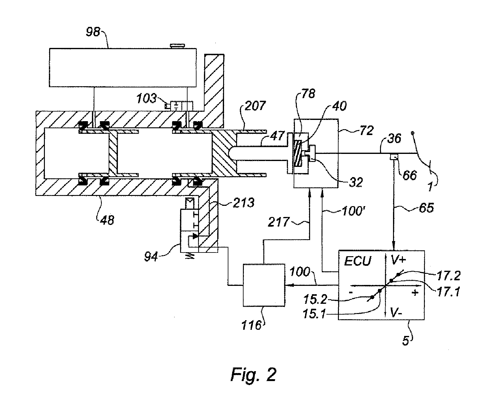
[0025]In FIGS. 1 to 6, the same references are used to denote the same elements.

[0026]FIG. 1 shows a braking system comprising a brake pedal 1 that drives a control rod 36 which, in turn, presses against a brake booster 72. The brake booster 72 applies a force to a thrust rod, which force is amplified by the brake booster 72.

[0027]The booster 72 is, for example, a pneumatic brake booster, a hydraulic brake booster, an electrical brake booster or the like. Typically, the booster 72 is equipped with a reaction device, typically a reaction disk made of non-compressible elastomer, and which transmits to the control rod 36 part of the reaction to the thrust applied to the thrust rod 47.

[0028]The thrust rod 47 presses, on command, against a primary piston 207 of a master cylinder 48. In the advantageous embodiment illustrated, the master cylinder 48 is a tandem master cylinder, with resupply via a resupply chamber situated between two cups and resupply holes situated in the piston. Howeve...


PUM


Abstract

The present invention relates mainly to a braking system comprising a master cylinder comprising means of connection to a hydraulic braking circuit and means of connecting at least one chamber of the master cylinder to means of injecting brake fluid into said chamber. The main subject of the invention is a master cylinder (48) comprising at least one variable-volume chamber and one moving piston (207), the movement of which causes the volume of said chamber to vary, and means of connecting said chamber to a hydraulic braking circuit, characterized in that it further comprises means (217) of connection to a source (116) of pressurized brake fluid. The invention applies notably to the motor industry. The invention applies mainly to the braking industry.

Description

BACKGROUND OF THE INVENTION[0001]The present invention relates mainly to a braking system comprising a master cylinder comprising means of connection to a hydraulic braking circuit and means of connecting at least one chamber of the master cylinder to means of injecting brake fluid into said chamber.[0002]It is known practice to produce brake boosters that apply a force to a thrust rod of a master cylinder which force is an increasing function of the force applied by the driver to a control rod via a brake pedal.[0003]It is also known practice to use a pedal feel simulator connected to a pedal fitted with brake setpoint sensors associated with a booster producing said setpoint. At the expense of increased complexity and increased fragility, devices incorporating a simulator allow decoupling between the position of a brake pedal and the hydraulic pressure available in the braking circuits. Likewise, WO 2007 / 080106 and WO 2007 / 080158, which are incorporated into this patent applicatio...

Claims


Application Information

Patent Timeline
Patent Type & Authority Patents(United States)
IPC IPC(8): F15B7/08B60T13/128
CPCB60T8/441B60T13/686B60T8/446B60T7/042B60T13/145B60T8/4845
Inventor CAGNAC, BASTIENANDERSON, CHRISSPROCQ, RAYNALD
Owner ROBERT BOSCH GMBH
Why Eureka
Try Eureka