Method for boosting the brake power in an electronically slip-controllable vehicle brake system, as well as an electronically slip-controllable vehicle brake system

a technology of electronic slip control and vehicle brake, which is applied in the direction of braking system, vehicle sub-unit features, braking components, etc., can solve the problems of considerable initial force needed to achieve a braking action, the force that the driver requires for this purpose is naturally significantly higher, and the disadvantage of a brake boost by the traction-slip control devi

Active Publication Date: 2020-12-29
ROBERT BOSCH GMBH
View PDF23 Cites 0 Cited by
  • Summary
  • Abstract
  • Description
  • Claims
  • Application Information

AI Technical Summary

Benefits of technology

[0013]A method according to the present invention has the advantage over this discussed related art of requiring less initial force for activating a hydraulic boosting of the traction-slip control device and, consequently, of providing the driver with an improved pedal feel, especially when the method is implemented in response to a malfunction in the power brake unit. The proposed method at least partly resorts to already existing sensor signals, is implemented in the electronic control unit, and does not result in any appreciable further constructional outlay.

Problems solved by technology

However, there are disadvantages to a brake boost by the traction-slip control device.
However, without an active brake booster, the force that the driver requires for this purpose is naturally significantly higher than when brake boost is present.
As a result, considerable initial force is needed to achieve a braking action, and the braking comfort is reduced correspondingly.
Moreover, in response to fluctuations in the pressure signal due to different malfunctions, the hydraulic brake boost can only be activated by the traction-slip control device when a limit value of the master cylinder pressure is exceeded.

Method used


Image

  • Method for boosting the brake power in an electronically slip-controllable vehicle brake system, as well as an electronically slip-controllable vehicle brake system
  • Method for boosting the brake power in an electronically slip-controllable vehicle brake system, as well as an electronically slip-controllable vehicle brake system
  • Method for boosting the brake power in an electronically slip-controllable vehicle brake system, as well as an electronically slip-controllable vehicle brake system

Examples


Embodiment Construction

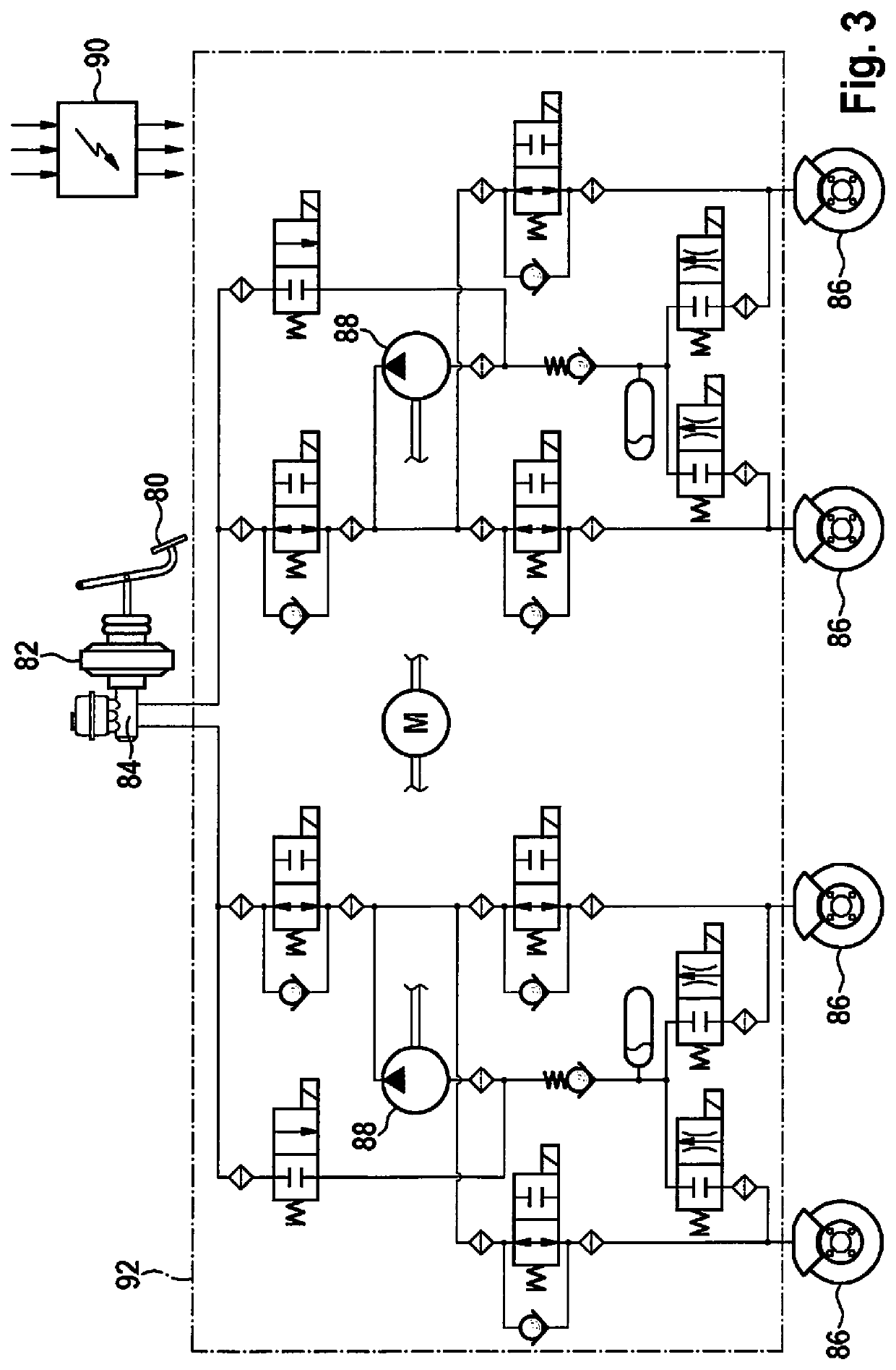
[0018]The method described in the following is used for a vehicle brake system, which, as explained at the outset and shown in FIG. 3, is at least equipped with an actuating device 80, a power brake unit 82, a brake master cylinder 84, a traction-slip control device 92, and a wheel brake 86 that able to be pressurized with brake pressure.

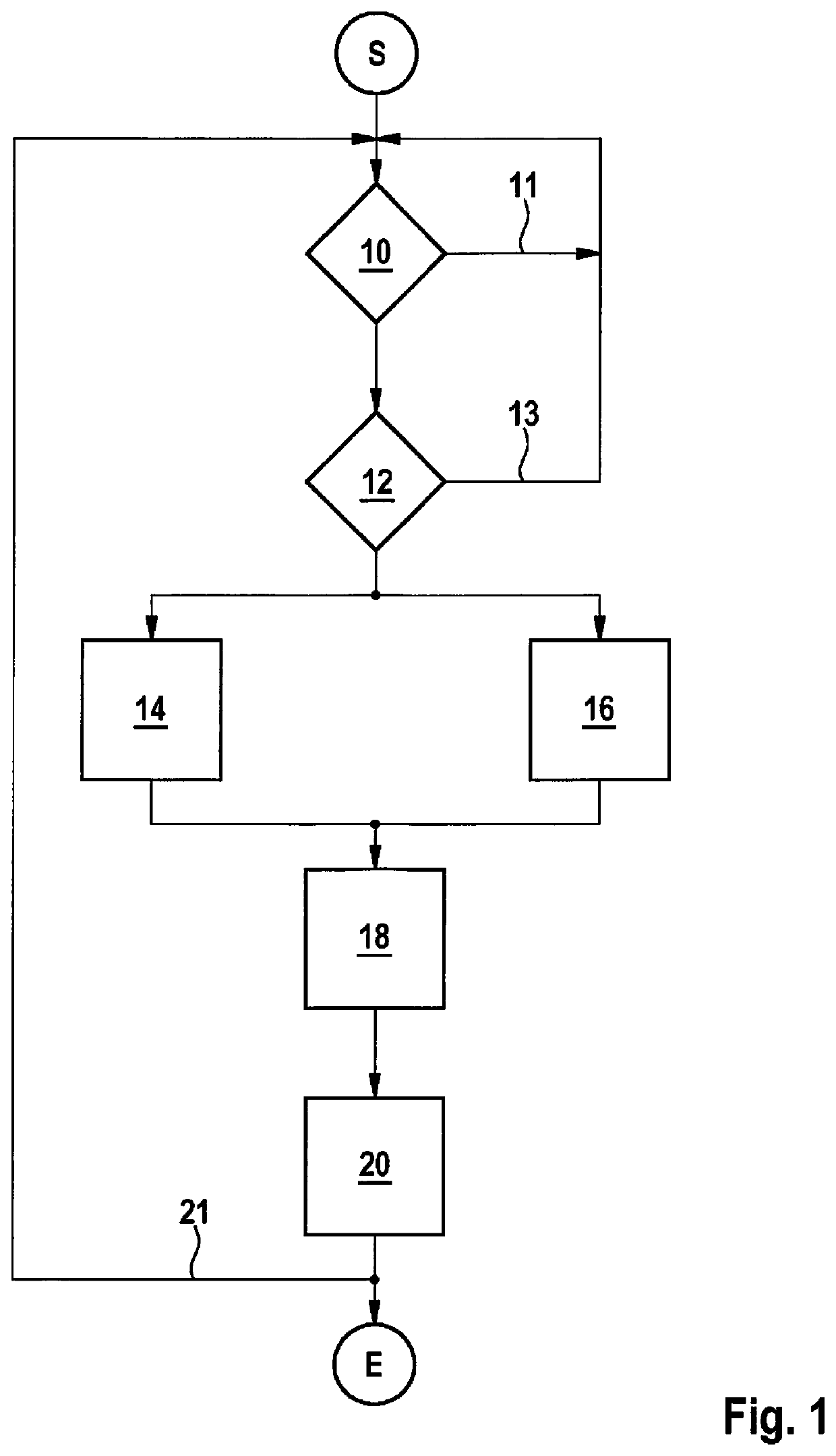
[0019]The method illustrated with reference to FIG. 1 and underlying the present invention is stored in the form of program steps of a computer program in an electronic control unit 90 of a vehicle brake system that is associated with traction-slip control device 92. The beginning or start and end of the method are characterized in FIG. 1 by symbols S and E.

[0020]A first step 10 following the start of the method is to check the vehicle brake system with respect to a malfunction or defect in the power brake unit.

[0021]This examination may be performed, for example, by ascertaining whether an input means of the power brake unit, via which the power br...


PUM


Abstract

A method for boosting a braking force in an electronically slip-controllable vehicle brake system, as well as an electronically slip-controllable vehicle brake system. Vehicle brake systems of this kind are at least equipped with a power brake unit and electronic slip-controllable vehicle brake system. In the case of a malfunction of the power brake unit, the traction-slip control device (92) takes over the boosting. A method for determining a composite signal which is adjusted by controlling a drive of a pressure generator of the slip-controllable vehicle brake system accordingly. To this end, an electronic control unit records two mutually independent input quantities, converts these input quantities into evaluation signals and sums the evaluation signals mathematically to yield a composite signal. The latter represents a setpoint brake pressure that the slip-controllable vehicle brake system supplies by controlling a pressure generator accordingly.

Description

FIELD OF THE INVENTION[0001]The present invention relates to a method for boosting the braking force in an electronically slip-controllable vehicle brake system, and to an electronically slip-controllable vehicle brake system.BACKGROUND INFORMATION[0002]Electronically slip-controllable vehicle brake systems are reasonably well known from the related art; they are often also referred to as ABS, ASC or ESP brake systems. In this regard, reference is made, for example, to the German Published Patent Application No. 10 2005 035 595.[0003]The basic design of this known slip-controllable vehicle brake system underlies the present invention. It is, therefore, shown in FIG. 3 for the sake of completeness.[0004]The slip-controllable vehicle brake system is equipped with an actuating device 80, for example, in the form of a conventional brake pedal, via which the driver inputs his / her brake intention as needed. Actuating device 80 is coupled exemplarily to a pneumatic power brake unit 82, whi...

Claims


Application Information

Patent Timeline
Patent Type & Authority Patents(United States)
IPC IPC(8): B60T13/14B60T13/68B60T13/66B60T8/88B60T8/44B60T8/40B60T8/1761B60T7/04
CPCB60T13/686B60T8/885B60T13/662B60T8/4072B60T8/442B60T7/042B60T8/17616B60T13/146B60T2270/402B60T2201/03B60T2220/04B60Y2400/81B60Y2400/30
Inventor HAAG, FLORIANVOLLERT, HERBERTKOLARSKY, JENS
Owner ROBERT BOSCH GMBH
Why Eureka
Try Eureka