Brake device for a motorcycle

a technology for brake devices and motorcycles, applied in brake systems, vehicle components, transportation and packaging, etc., can solve problems such as substantial discomfort, achieve the effect of avoiding discomfort felt by riders, preventing hydraulic pressure, and improving breaking operation feeling and control

Active Publication Date: 2010-09-30
HONDA MOTOR CO LTD
View PDF7 Cites 2 Cited by
  • Summary
  • Abstract
  • Description
  • Claims
  • Application Information

AI Technical Summary

Benefits of technology

[0018]According to one embodiment, a target hydraulic pressure acting on the front wheel braking unit is corrected using a preset prescribed function. This correction is performed in such a manner that the braking force becomes smaller than a braking force corresponding to an additional operation of the front wheel braking operation unit when the front wheel braking operation unit is generating braking force as a result of combined braking configured so that the rear wheel braking unit and the front wheel braking unit are combined based on the operation of the rear wheel braking operation unit so as to be capable of being controllably driven. As a result, it is possible to effectively prevent hydraulic pressure based on the additional operation from simply being added to hydraulic pressure acting as a result of existing combined braking. Similarly, it is possible to prevent the braking force at the front wheel braking unit from becoming abruptly high, and discomfort felt by the rider is avoided. It is also therefore possible to improve breaking operation feeling and control.
[0019]According to another embodiment, the correction is carried out so as to give a rise in hydraulic pressure in line with a tendency of the brake hydraulic pressure of the front wheel braking unit generated in combination with the operation of the rear wheel braking operation unit to rise. As a result, it is possible to suppress a feeling of discomfort between the break operation and the braking force to as great an extent is possible, and the feeling of the break operation and control are therefore both improved dramatically.
[0020]According to another embodiment, when the target hydraulic pressure at the front wheel braking unit is decided by adding the corrected target additional hydraulic pressure to the hydraulic pressure at the front wheel braking unit acting as a result of the combined braking, the target hydraulic pressure provided to the front wheel braking unit can be appropriately corrected and the brake operation feeling and control can be improved.
[0021]According to another embodiment, when the target additional hydraulic pressure is corrected using a correction coefficient set in advance using a relationship with a magnitude of hydraulic pressure of the front wheel braking unit, it is possible to appropriately add hydraulic pressure to the hydraulic pressure currently acting at the front wheel braking unit even when there is an additional operation of the front wheel braking operation unit.
[0022]According to another embodiment, when the prescribed function is a function that corrects the target additional hydraulic pressure using a prescribed rate of decreasing, the occurrence of an abrupt rise in the braking force at the front wheel braking unit as the result of an additional operation of the front wheel brake operation unit can be reliably avoided.
[0023]According to another embodiment, when the correction coefficient is a map set in advance correlated to the magnitude of the hydraulic pressure of the front wheel braking unit, it is possible to implement an operation relating to correction of the target additional hydraulic pressure in a much more straightforward manner. It is therefore possible to easily provide compatibility with different models and changes to specifications by only changing the map. This reduces both a number of steps and the cost.

Problems solved by technology

As a result, there is the possibility of front wheel side brake control (braking behavior) causing discomfort.
In particular, there is the possibility of substantial discomfort being experienced by a driver driving a motorcycle that is not mounted with a CBS.

Method used


Image

  • Brake device for a motorcycle
  • Brake device for a motorcycle
  • Brake device for a motorcycle

Examples


Embodiment Construction

[0029]The following is a detailed description of a brake device for a motorcycle, according to one embodiment, referring to the appended drawings.

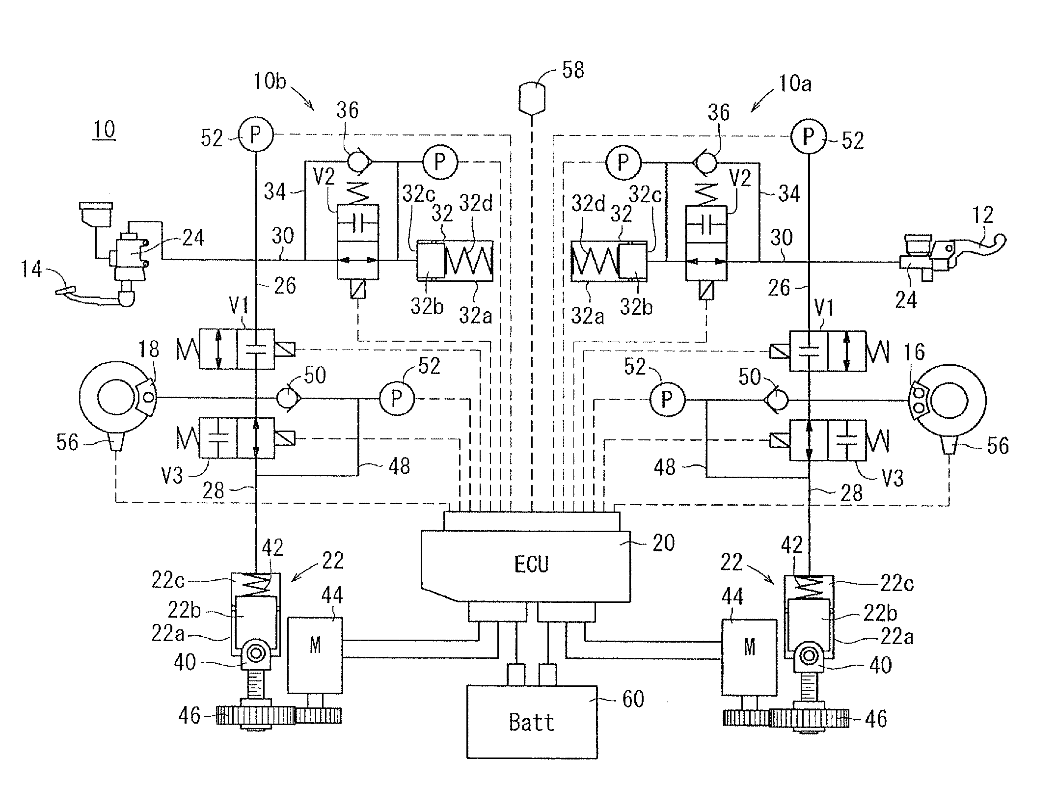
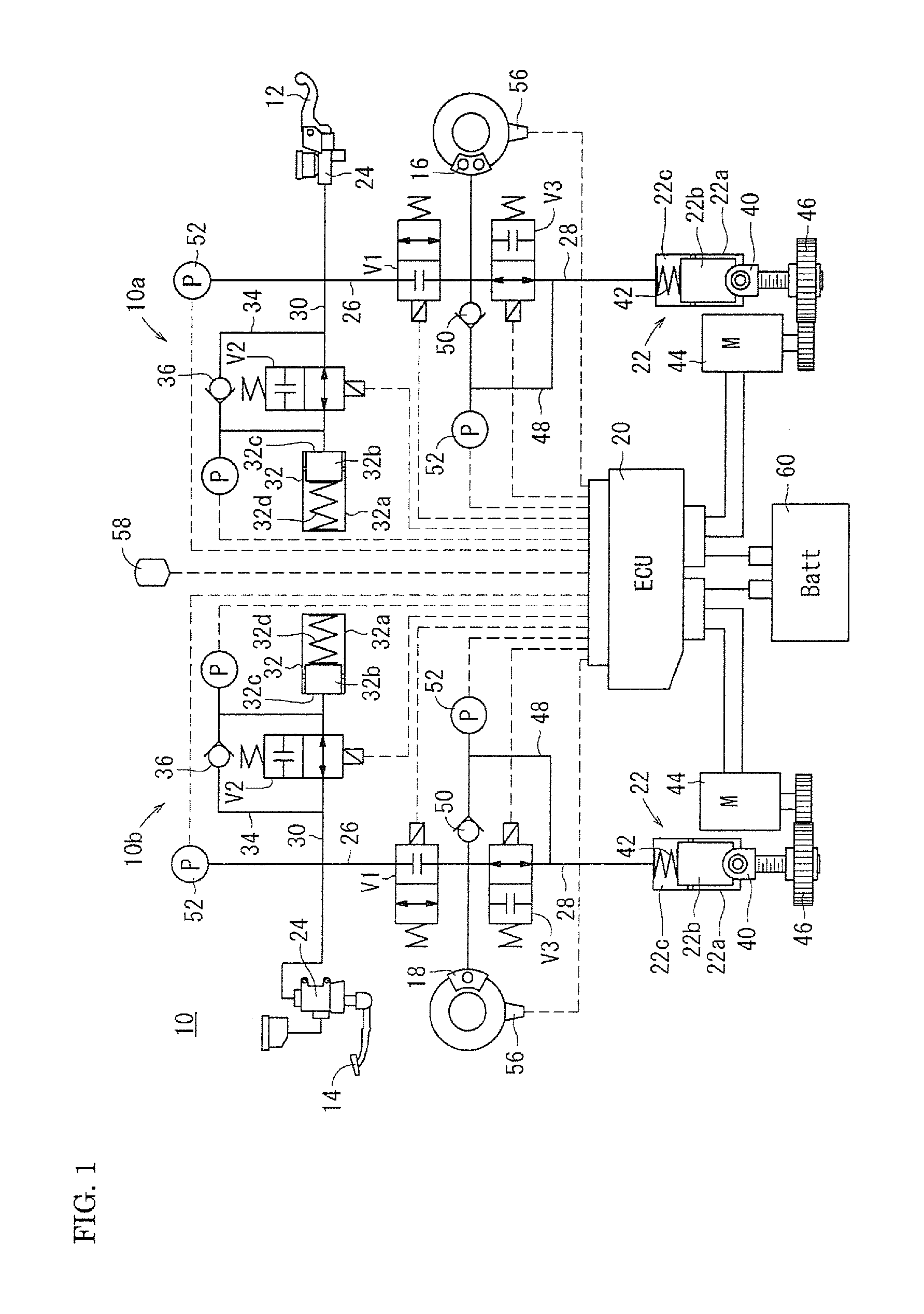
[0030]FIG. 1 is a circuit diagram showing a configuration for a brake device 10 for a motorcycle according to one embodiment of the present invention. The brake device 10 (can be mounted on various motorcycles. A front wheel brake caliper 16 and a rear wheel brake caliper 18 are driven and controlled by the operation of a brake lever 12 and a brake pedal 14 by the driver (rider) so as to provide a prescribed braking force for the vehicle.

[0031]As shown in the example of FIG. 1, the brake device 10 can be an independently provided front wheel brake circuit 10a and rear wheel brake circuit 10b linked by an ECU (controller, control unit) 20.

[0032]At the brake device 10, a braking operation is carried out using the brake lever 12 that is a front wheel brake operation unit at the front wheel brake circuit 10a and is carried out using the brake ...


PUM


Abstract

A brake device 10 for a motorcycle is capable of electrically performing driving so as to control a front wheel brake caliper 16 and a rear wheel brake caliper 18 in response to each operation of a brake lever 12 and a brake pedal 14 and is configured so that the rear wheel brake caliper 18 and the front wheel brake caliper 16 can be combined based on the operation of the brake pedal 14. The brake device 10 performs correction of a target hydraulic pressure acting on the front wheel brake caliper 16 using a prescribed preset function in such a manner as to give a braking force smaller than a braking force corresponding to an additional operation of the brake lever 12 when the brake lever 12 is additionally operated in the state where the brake pedal 14 is operated and the front wheel brake caliper 16 is generating braking force in combination with the rear wheel brake caliper 18.

Description

BACKGROUND[0001]1. Field[0002]Embodiments of the present invention relate to a brake device for a motorcycle. The brake device enables, for example, a rear wheel braking unit and a front wheel braking unit to operate in combination based on operation of the rear wheel braking operation unit so as to enable drive control.[0003]2. Description of the Related Art[0004]A combined brake system (CBS) in a motorcycle brake device is a system where hydraulic pressure actuates a braking unit when the brake operation unit (brake lever or brake pedal) of a front wheel or a rear wheel is operated. A prescribed amount of hydraulic pressure also actuates the braking unit for the wheel on the side that is not operated.[0005]For example, devices that control braking force distribution across a front wheel braking unit and a rear wheel braking unit are disclosed in Japanese Patent Publication Laid-open No. Hei. 11-5580, Japanese Patent Publication Laid-open No. 2005-239134, and Japanese Patent Public...

Claims


Application Information

Patent Timeline
Patent Type & Authority Applications(United States)
IPC IPC(8): B60T13/66
CPCB60T8/261B60T13/662B60T8/4081B60T8/3225
Inventor NISHIKAWA, YUTAKATAKENOUCHI, KAZUYANANRI, TAKEHIKOTANI, KAZUHIKO
Owner HONDA MOTOR CO LTD
Why Eureka
Try Eureka