Cam cap

a technology of cam caps and camshafts, applied in the direction of valve drives, machines/engines, auxilaries, etc., can solve the problems of pulsating pressure, fluctuation of oil pressure in the camshaft, fuel consumption deterioration, etc., and achieve the effect of preventing hydraulic pressur

Inactive Publication Date: 2010-06-03
HYUNDAI MOTOR CO LTD +1
View PDF2 Cites 1 Cited by
  • Summary
  • Abstract
  • Description
  • Claims
  • Application Information

AI Technical Summary

Benefits of technology

[0023]The flowing backward preventing member includes a plunger provided with a chamber therein and at least an oil opening may be formed to a side of the plunger for supplying a backward hydraulic pressure into the camber so as to move the plunger into the inlet channel when a backward flow of the operation oil occurs in the flowing backward preventing hole, wherein the plunger includes a main body and a protrude portion protruded from the main body, the plunger being movably disposed in the flowing backward preventing hole such that the protrude portion selectively blocks the inlet channel according to a flow direction of the operation oil, and wherein a lower end portion of the main body is shaped of a cone for smoothly supplying the hydraulic pressure between the inlet and outlet channels.
[0024]A check valve, for preventing the hydraulic pressure from supplied from the outlet channel to the inlet channel, may be disposed to the flowing backward preventing portion.

Problems solved by technology

However, repeated supplying and blocking operation oil can induce oil flowing backward resulted of pulsating pressure in the oil supply lines of the OCV and also fluctuation of oil pressure in the CVVT can be occurred.
However, excessive capacity of the hydraulic pump for preventing from fluctuation of oil pressure can induce fuel consumption deterioration.

Method used


Image

  • Cam cap
  • Cam cap
  • Cam cap

Examples


Embodiment Construction

[0034]Reference will now be made in detail to various embodiments of the present invention(s), examples of which are illustrated in the accompanying drawings and described below. While the invention(s) will be described in conjunction with exemplary embodiments, it will be understood that present description is not intended to limit the invention(s) to those exemplary embodiments. On the contrary, the invention(s) is / are intended to cover not only the exemplary embodiments, but also various alternatives, modifications, equivalents and other embodiments, which may be included within the spirit and scope of the invention as defined by the appended claims.

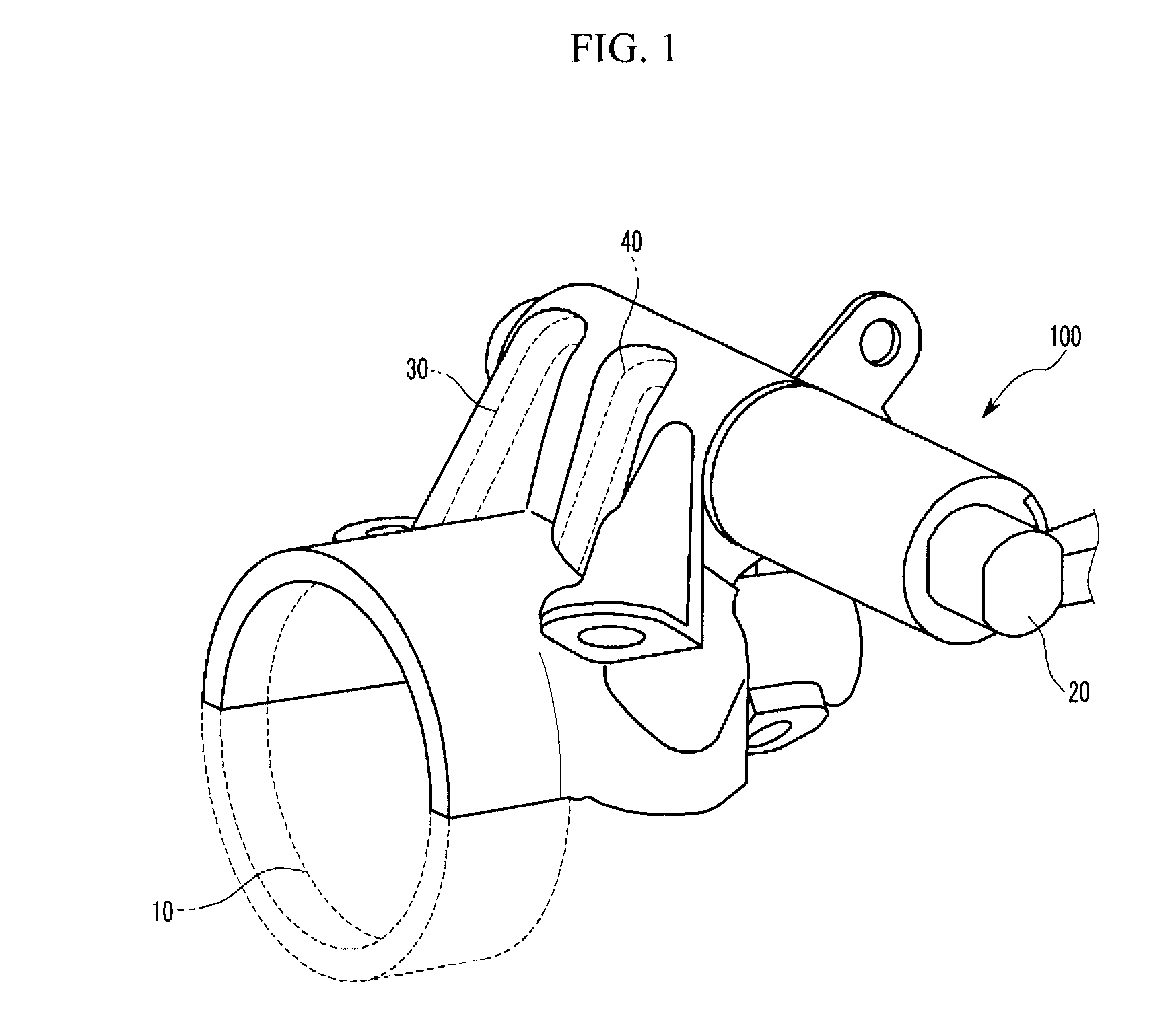
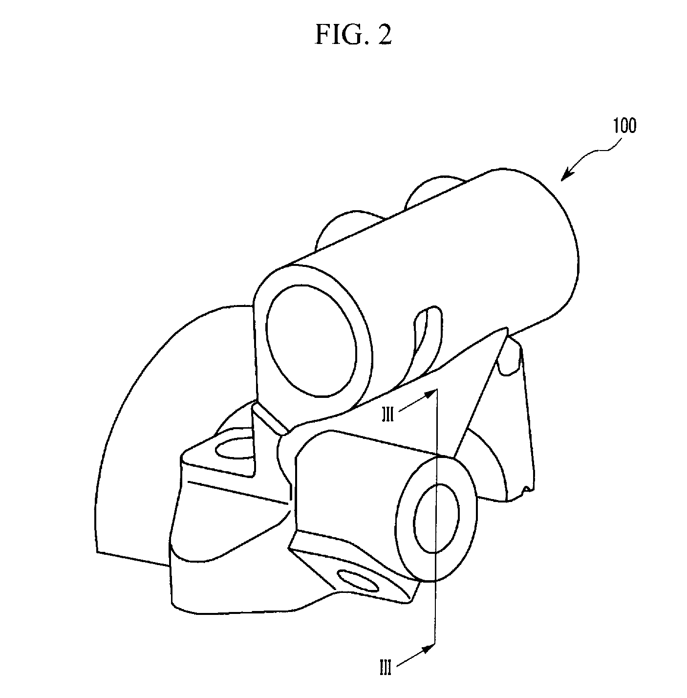
[0035]FIG. 1 is a perspective view of an exemplary cam cap according to the present invention and FIG. 2 is a perspective view of an exemplary cam cap without an oil control valve and a continuously variable valve timing according to the present invention.

[0036]FIG. 3 is a cross-sectional view along line III-III of FIG. 2.

[0037]Referr...


PUM


Abstract

A cam cap may include an oil supply circuit formed to the cam cap for supplying hydraulic pressure to a continuously variable valve timing and an oil flowing backward preventing unit disposed to the oil supply circuit for preventing operation oil from flowing backward.

Description

CROSS-REFERENCE TO RELATED APPLICATION[0001]The present application claims priority to Korean Patent Application No. 10-2008-0122133 filed on Dec. 3, 2008, the entire contents of which are incorporated herein for all purposes by this reference.BACKGROUND OF THE INVENTION[0002]1. Field of the Invention[0003]The present invention relates to a cam cap. More particularly, the present invention relates to a cam cap that prevent from flowing backward to a continuous variable valve timing.[0004]2. Description of Related Art[0005]A variable valve timing (CVVT; continuous variable valve timing) is a apparatus for controlling valve opening timing by supplying operation oil according to engine operation conditions and it can enhance fuel consumption efficiency.[0006]The CVVT is operated by supplied oil from advance / retard oil supply lines of an oil control valve (OCV; oil control valve).[0007]However, repeated supplying and blocking operation oil can induce oil flowing backward resulted of pul...

Claims


Application Information

Patent Timeline
Patent Type & Authority Applications(United States)
IPC IPC(8): F01M1/06
CPCF01L1/053F01L1/344F01M9/10F01L2810/02F01L2001/0476F01L1/04F01L1/34F01M1/06
Inventor JUNG, JAE HO
Owner HYUNDAI MOTOR CO LTD
Why Eureka
Try Eureka