Electrical connector for circuit board and electrical connector assembly

A circuit substrate and electrical connector technology, which is applied in the direction of two-component connection devices, parts of connection devices, circuits, etc., can solve the problems of limited board thickness and inability to realize connector locking, etc., and achieve the effect of reliable locking state

Active Publication Date: 2016-10-19
HIROSE ELECTRIC GROUP
View PDF5 Cites 0 Cited by
  • Summary
  • Abstract
  • Description
  • Claims
  • Application Information

AI Technical Summary

Problems solved by technology

However, the size of the portion of the locking piece that can be locked with respect to the locking protrusion can only be ensured to an amount corresponding to the plate thickness of the locking piece. Therefore, if the locking protrusion is arranged so as to If the board is staggered in the terminal arrangement direction by the amount corresponding to the thickness of the board, the locking of the connectors cannot be achieved.
In addition, the above-mentioned engaging piece is formed as a part of the socket-side locking metal fitting, so that its thickness is the same as that of other parts, so the above-mentioned plate thickness dimension is limited.

Method used


Image

  • Electrical connector for circuit board and electrical connector assembly
  • Electrical connector for circuit board and electrical connector assembly
  • Electrical connector for circuit board and electrical connector assembly

Examples


no. 1 approach >

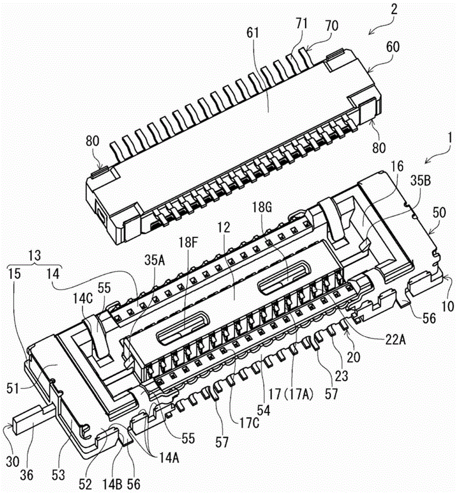
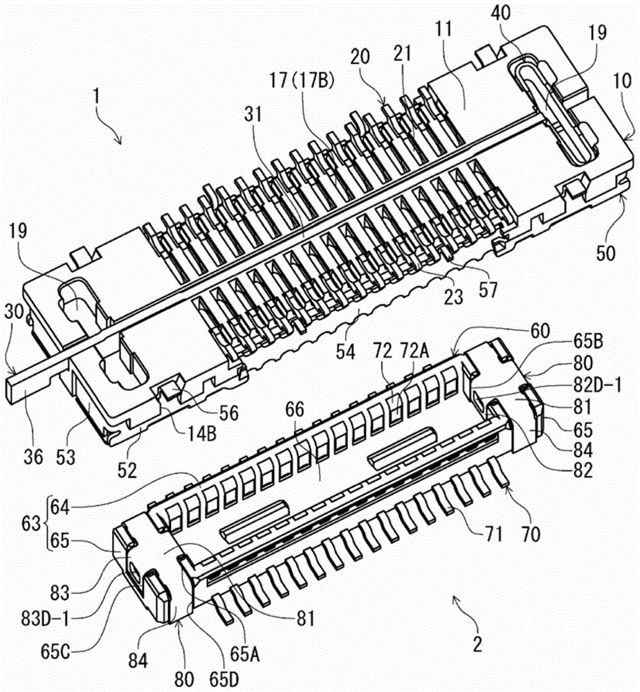
[0041] figure 1 It is a perspective view of the receptacle connector 1 according to this embodiment and the plug connector 2 fitted to the receptacle connector 1 from above, showing a state before the connectors are fitted. figure 2 will be figure 1 The perspective view in which the receptacle connector 1 and the plug connector 2 are shown upside down is shown in a posture in which the plug connector 2 is fitted from below.

[0042] The receptacle connector 1 and the mating connector plug connector 2 of the receptacle connector 1 in this embodiment are electrical connectors for circuit boards respectively arranged on the mounting surfaces of different circuit boards (not shown), and constitute In the direction at right angles to the surface of each circuit board ( figure 1 The up and down direction) is the connector assembly in the plugging direction.

[0043] like figure 1 As shown, the receptacle connector 1 has: a receptacle-side housing 10, the receptacle-side housing...

no. 2 approach >

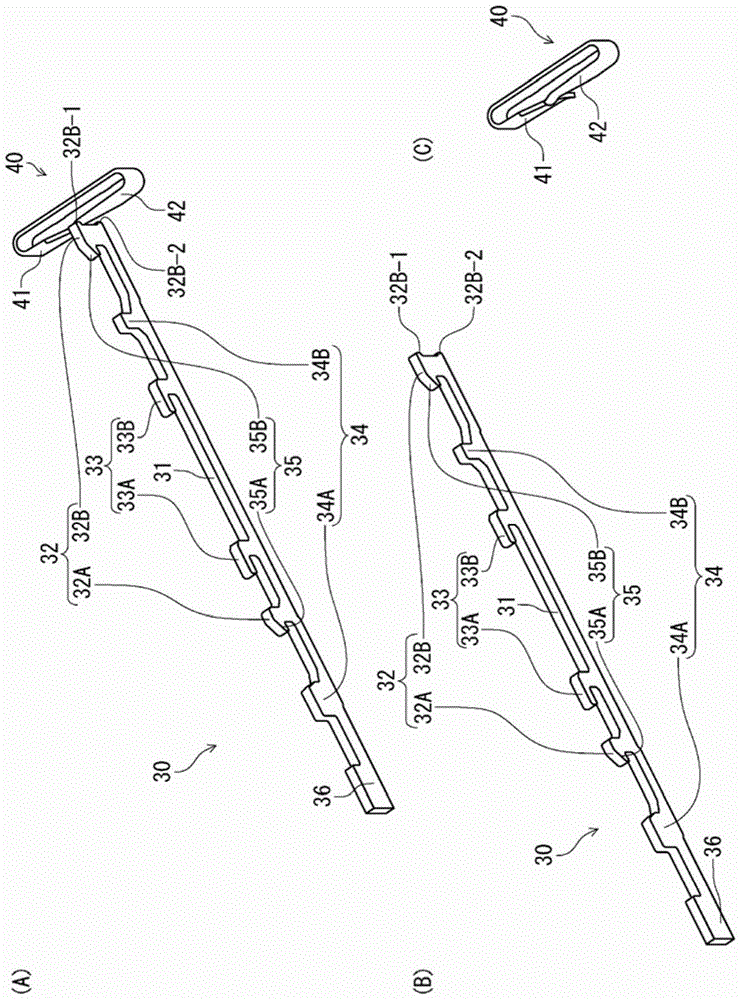
[0102] In the first embodiment, the socket connector 1 is provided with the locking metal piece 30 and the elastic deformation member 40, and the elastic deformation member 40 applies force to the locking metal piece 30. However, in this embodiment, no elastic deformation member is provided. It is different from the first embodiment in that the locking metal fitting itself has an elastically deformable portion capable of elastically deforming in the direction in which the terminals are arranged.

[0103] Figure 9 (A) is a perspective view showing the lock metal fitting 130 according to this embodiment. The locking metal fitting 130 of the present embodiment is produced by punching a metal plate into a predetermined shape, and then bending the metal plate in the thickness direction. like Figure 9 As shown in (A), the locking metal fitting 130 is formed so that two locking metal fittings 30 in the first embodiment are overlapped, and the side edges of their second rising por...

no. 3 approach >

[0108] In the first embodiment, the elastically deformable member 40 is formed by bending a strip-shaped metal plate member, but in this embodiment, the elastically deformable member is not made of such a metal plate member but is made of a coil spring. , which is different from the first embodiment. Figure 10 (A) is a cross-sectional view showing part of the receptacle connector 201 according to this embodiment. In this embodiment, the description will focus on the differences from the first embodiment, and for the parts corresponding to the receptacle connector 1 in the first embodiment, "200" will be added to the reference numerals in the first embodiment. ” and its description is omitted.

[0109] Figure 10 (A) shows one end side portion of the receptacle connector 201 according to this embodiment (with Figure 5 The part corresponding to the left half in (B)). like Figure 10 As shown in (A), the receptacle connector 201 has an elastically deformable member 240 for...


PUM


Abstract

The present invention provides an electrical connector for a circuit board and an electrical connector assembly including the electrical connector for a circuit board and a mating connector, which can increase the protrusion amount of a locking portion of a locking member provided in the electrical connector for a circuit board, And the stable locking state of the locking parts can be ensured. The locking member (30) is stored in the storage portion of the housing (10), and the locking portions (35A, 35B) are movable between a locking position and a lock release position. The locking position is where the locking portions (35A, 35B) face the receiving portion ( 16) A position that protrudes and is locked with the locked portion of the mating connector (2). This unlocking position is when the locking portion (35A, 35B) moves toward the other end wall (15) side in the terminal arrangement direction. When the lock is released, the elastic deformation portion (40) exerts an urging force on the locking member (30) to move the locking member (30) toward the locking position.

Description

technical field [0001] The present invention relates to an electrical connector for a circuit board and an electrical connector assembly, wherein the electrical connector is arranged on a mounting surface of a circuit board, and a direction at right angles to the mounting surface is a connector insertion and extraction direction and The mating connector located above is fitted and connected, and the electrical connector assembly includes the electrical connector for the circuit board and the mating connector. Background technique [0002] Such an electrical connector assembly is disclosed in Patent Document 1, for example. For the electrical connector assembly in this patent document 1, the receptacle connector is mounted on one circuit board, and the plug connector serving as a mating connector is mounted on the mounting surface of the other circuit board. In the state where the mounting surfaces of the two connectors are parallel, the two connectors are mated and connecte...

Claims


Application Information

Patent Timeline
Patent Type & Authority Patents(China)
IPC IPC(8): H01R13/639H01R12/51H01R24/00
CPCH01R12/73H01R12/714H01R12/716H01R13/639G02B6/3879
Inventor 绿川和弥
Owner HIROSE ELECTRIC GROUP
Why Eureka
Try Eureka