Distributed matrix switching system

A matrix switching and distributed technology, which is applied to the parts of TV systems, TVs, and color TVs, etc., can solve the problems of not being able to add signal sources at will, affecting the system, and affecting the overall aesthetics of difficult projects such as engineering construction , to achieve the effect of long-distance transmission

Inactive Publication Date: 2014-10-22
无锡思朗电子科技有限公司
View PDF4 Cites 13 Cited by
  • Summary
  • Abstract
  • Description
  • Claims
  • Application Information

AI Technical Summary

Problems solved by technology

This realistic technology mainly has the following defects: the whole project cannot increase the number of signal sources and the number of splicing screens at will; multiple professional signal cables will be used (the number of cables is related to the number of signal sources and the number of splicing screens), This will greatly affect the difficulty of engineering construction and the overall aesthetics of the project; the transmission distance of professional cables is limited; once the matrix switcher fails, it will affect the entire system

Method used


Image

  • Distributed matrix switching system
  • Distributed matrix switching system
  • Distributed matrix switching system

Examples


Embodiment 1

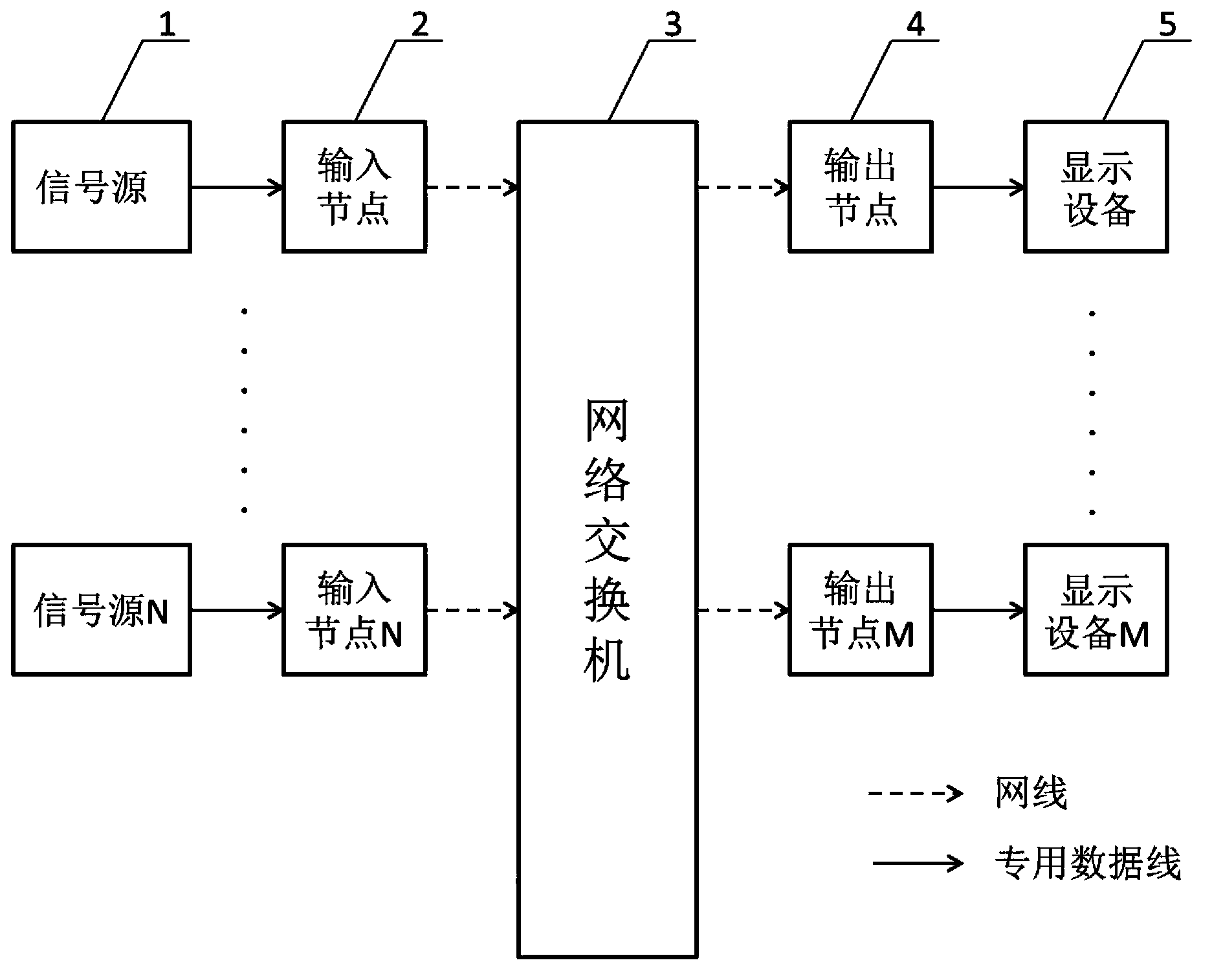
[0021] Such as figure 1 As shown, a distributed matrix switching system includes a signal source 1, at least one input node 2, a network switch 3, at least one output node 4 and a display device 5, the signal source 1, input node 2, network switch 3 , the output node 4, and the display device 5 are connected in sequence. There are N number of input nodes 2 and signal sources 1 , and M number of output nodes 4 and display devices 5 . The input node 2 is connected to the signal source 1 through a dedicated data cable (DVI cable, VGA cable or composite video cable, etc.), and the output node 4 is also connected to the display device 5 through a dedicated data cable.

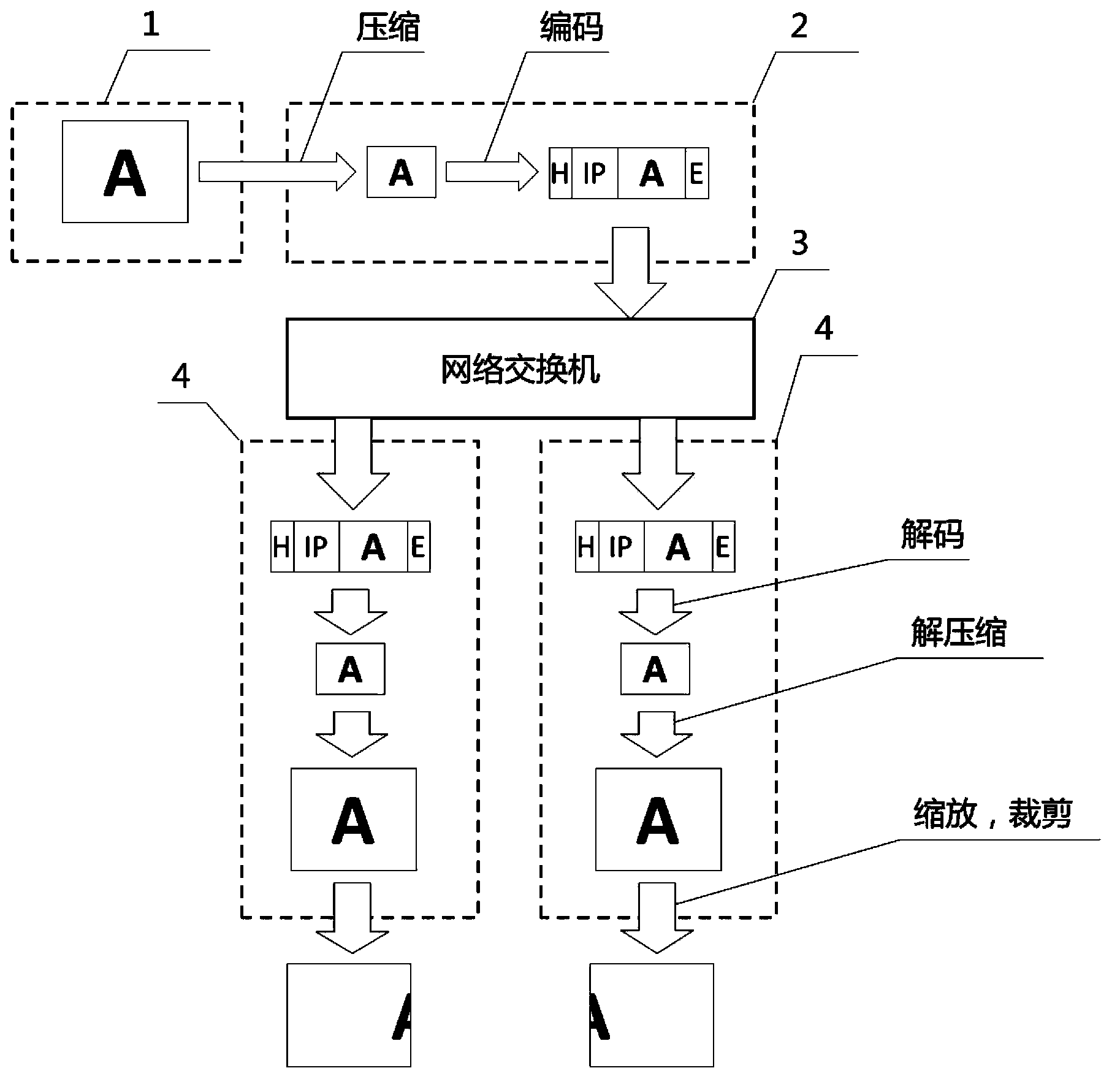
[0022] Such as figure 2 As shown, after the image signal of the signal source 1 is input to the input node 2, the input node 2 compresses and encodes it into network data and sends it to the network switch 3. After the output node 4 receives the network data through the network switch 3, it processes the network ...

Embodiment 2

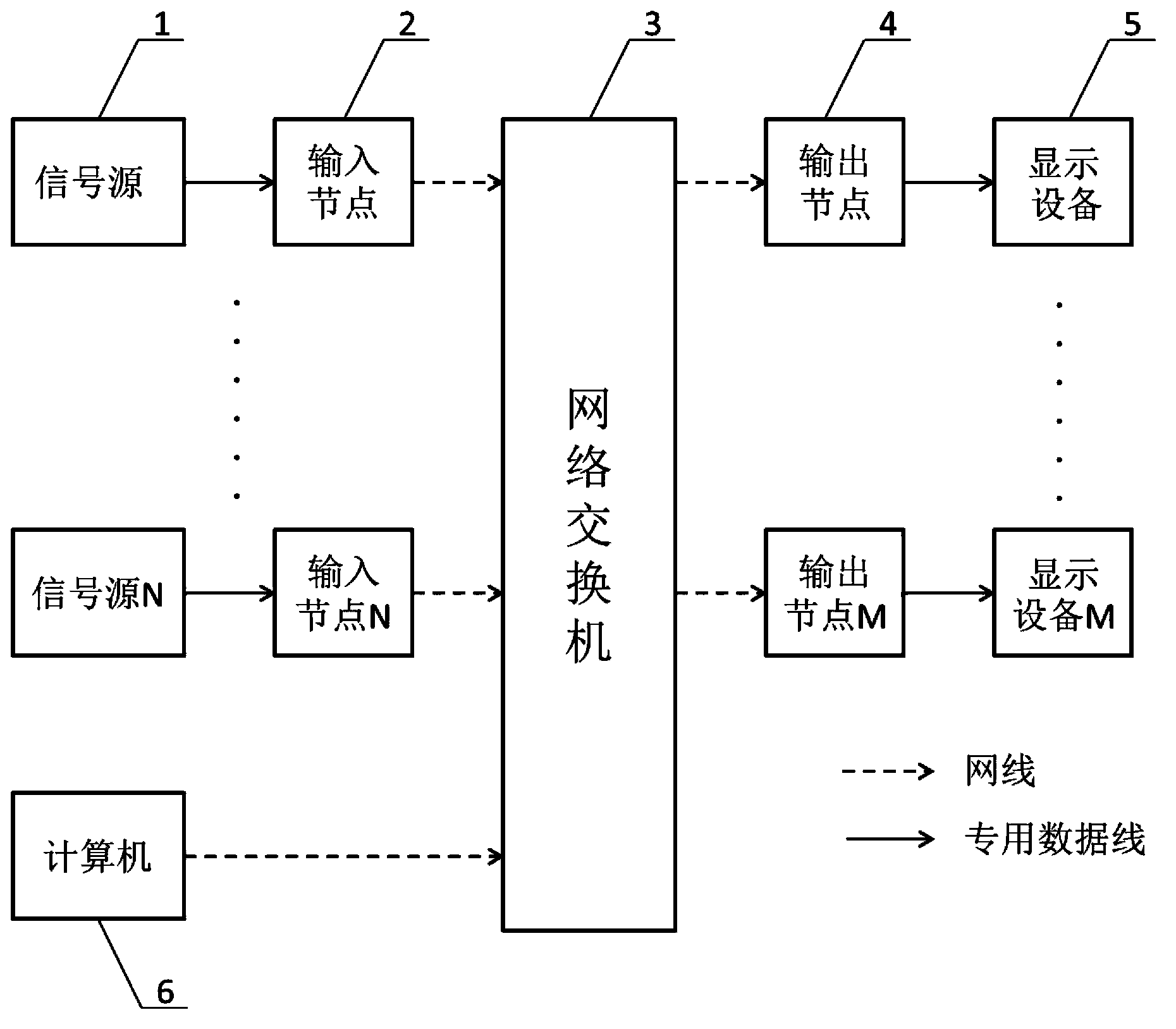
[0026] Such as image 3 As shown, a distributed matrix switching system includes a signal source 1, at least one input node 2, a network switch 3, at least one output node 4, a display device 5 and a computer 6, the signal source 1, input node 2, Network switch 3, output node 4, display device 5 are connected in sequence, and described computer 6 is connected with output node 4 through network switch 3, and computer sends output node start-up signal through network switch, selects to use different input nodes, and sends output node Send image scaling and cropping specifications in real time to control the scaling and cropping operations of output nodes. All the other parts are the same as in Example 1.


PUM


Abstract

The invention relates to a distributed matrix switching system comprising a signal source, at least one input node, a network switch, at least one output node, and a display device that are connected successively. After an image signal of the signal source is inputted into the input node, the input node compresses and encodes the image signal into network data and then transmits the network data to the network switch. After receiving the network data via the network switch, the output node decompresses, zooms, and cuts the network data and then outputs processed data to the display device. Then, the display device displays images. Compared with a product in the prior art, the distributed matrix switching system has advantages of good expansibility, convenient maintenance, and real-time signal transmission.

Description

technical field [0001] The invention relates to a video transmission and display technology, in particular to a distributed matrix switching system. Background technique [0002] At present, with the development of video splicing display technology, large-screen splicing video walls have gained more and more favor for their high-definition, vivid colors, and large-screen effects. The high resolution of the splicing large screen can convey more information, and can meet the needs of real-time monitoring, command and dispatch, report display, advertising and other aspects, and has been widely used in a large area. [0003] The existing splicing display technology is usually realized in the following way: the image information of multiple signal sources is transmitted to a centralized matrix switcher through professional cables, and the matrix switcher is then transmitted to the corresponding splicing screen through cables. This realistic technology mainly has the following de...

Claims


Application Information

Patent Timeline
Patent Type & Authority Applications(China)
IPC IPC(8): H04N5/268
Inventor 刘正
Owner 无锡思朗电子科技有限公司
Why Eureka
Try Eureka