

Optical sensing based impulse testing method and device
An impulse test and optical sensing technology, applied in measuring devices, force/torque/work measuring instruments, instruments, etc., can solve the problems affecting the accuracy and reliability of test signals, complicated design, processing and data processing, and the inability of test circuits. Problems such as normal work, to achieve the effect of compact structure, improved anti-electromagnetic interference ability, and easy installation and disassembly
- Summary
- Abstract
- Description
- Claims
- Application Information
AI Technical Summary
Problems solved by technology
Method used
Image


Examples
Embodiment Construction
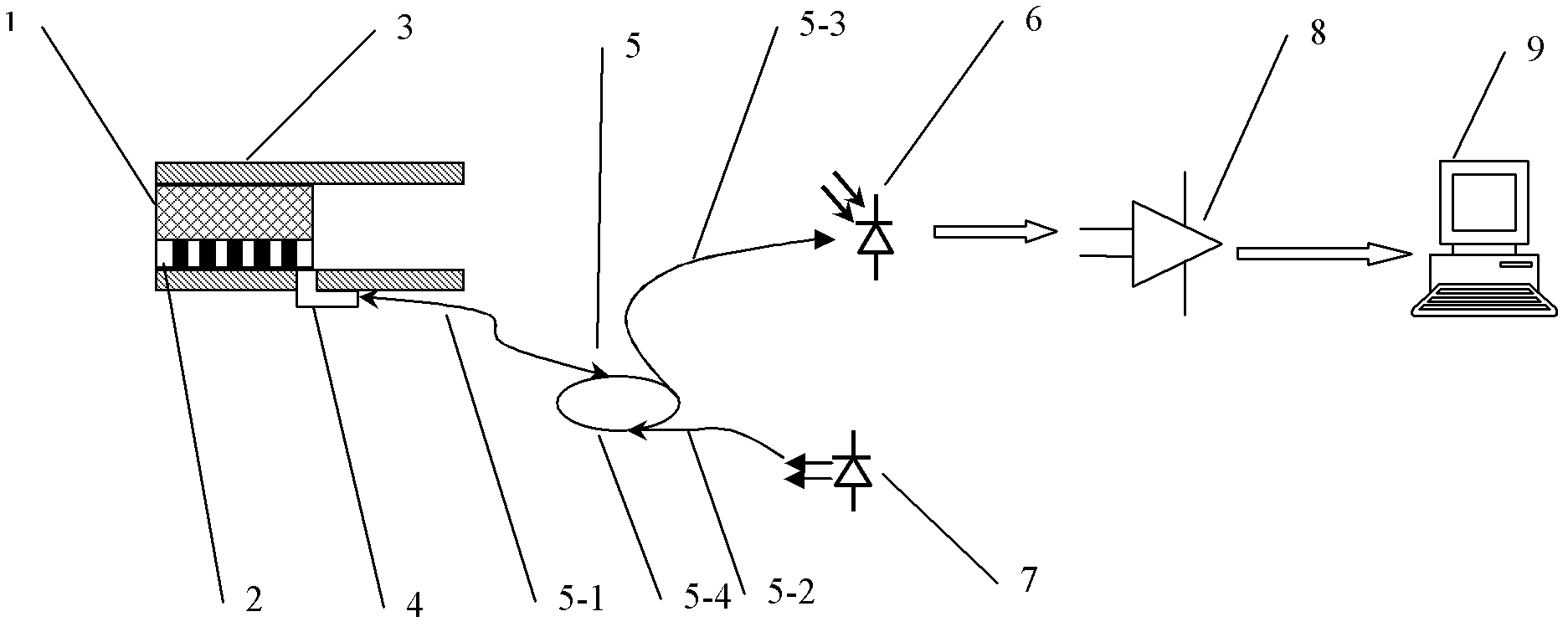
[0036] Such as figure 1 As shown, the technical solution adopted in the present invention is to install the linear grating 2 horizontally on the mass block 1, and make the grating not affect the free movement of the mass block 1 in the guide rail 3 along the direction of the guide rail 3. The optical fiber probe 5 is installed on the guide rail 3 so that the light emitted by the optical fiber probe 5 is perpendicular to the linear grating 2 so that the light reflected by the grating can enter the optical fiber probe 5 . The impulse parameter is calculated by measuring the reflected light intensity-time curve of the mass block 1 moving along the guide rail 3 under the action of impulse.
[0037] The linear grating 2 provides displacement resolution information in the direction of the guide rail 3 . The grating is composed of materials with different light reflectivity at repeated intervals. The part composed of high reflectivity materials is called light pattern, and the mater...
PUM
| Property | Measurement | Unit |
|---|---|---|
| Core diameter | aaaaa | aaaaa |
| Wavelength | aaaaa | aaaaa |
| Grid pitch | aaaaa | aaaaa |
Abstract
Description
Claims
Application Information