Eureka AIR delivers breakthrough ideas for toughest innovation challenges, trusted by R&D personnel around the world.

Portable very-fast transient high-frequency magnetic field measurement system

A measurement system and high-frequency magnetic field technology, which is applied in the direction of the size/direction of the magnetic field, can solve the problems that the magnetic field measurement technology and devices cannot meet the measurement requirements, and improve the ability to resist electromagnetic interference, reduce power consumption, and save storage capacity. Effect

Pending Publication Date: 2019-08-27
ELECTRIC POWER SCI RES INST OF GUIZHOU POWER GRID CO LTD
View PDF0 Cites 0 Cited by
  • Summary
  • Abstract
  • Description
  • Claims
  • Application Information

AI Technical Summary

Problems solved by technology

[0003] The magnetic field generated by the switching operation of GIS substation is a kind of ultra-fast transient high-frequency magnetic field that appears along with the electromagnetic transient state of switching operation. It has the characteristics of steep rising edge of magnetic field pulse, rapid amplitude change and high frequency. The main technical index parameters are: The frequency is mainly distributed in the range of 1MHz to 60MHz, and the field strength (peak-peak value) ranges from 80A / m to 110A / m. These characteristics of the ultra-fast transient high-frequency magnetic field make the existing magnetic field measurement technology and devices unable to meet its measurement requirements.

Method used


Image

  • Portable very-fast transient high-frequency magnetic field measurement system
  • Portable very-fast transient high-frequency magnetic field measurement system
  • Portable very-fast transient high-frequency magnetic field measurement system

Examples


Embodiment Construction

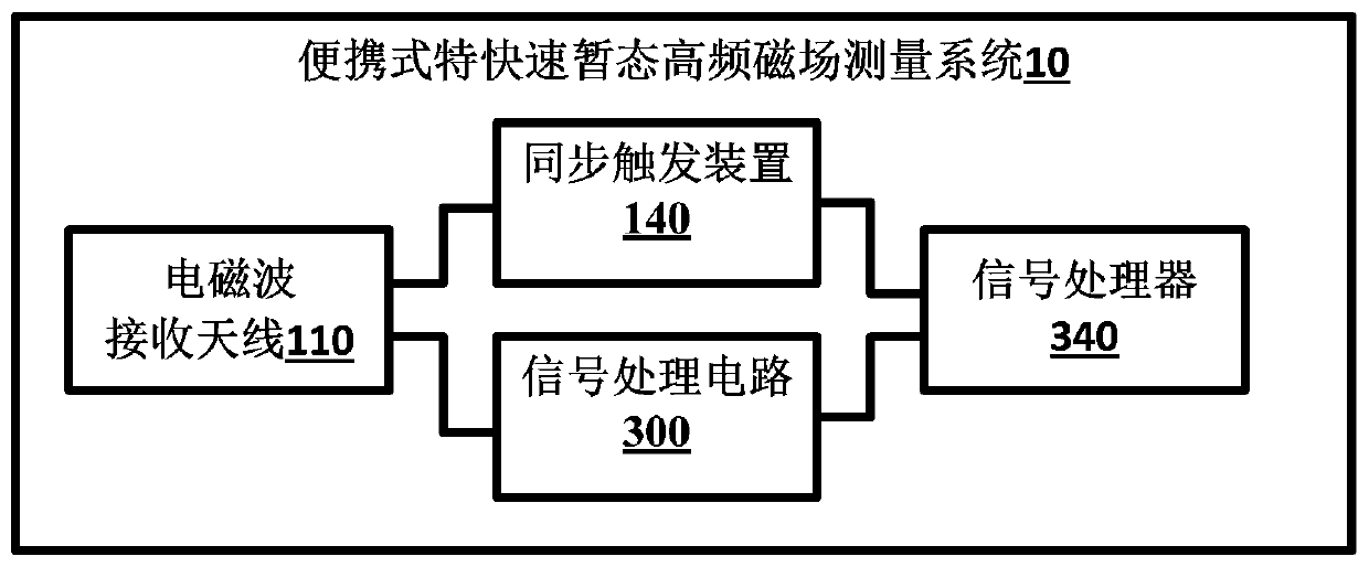
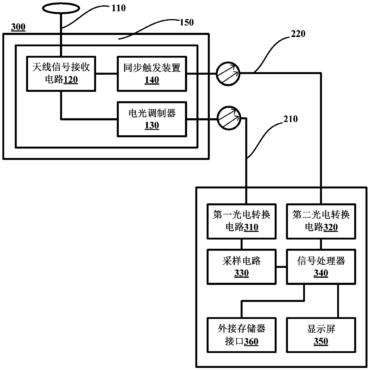
[0046] figure 1 is a schematic diagram of a portable ultra-fast transient high-frequency magnetic field measurement system 10 according to an embodiment of the present invention. The portable ultra-fast transient high-frequency magnetic field measurement system 10 may generally include: an electromagnetic wave receiving antenna 110 , a synchronous trigger device 140 , a signal processing circuit 300 , and a signal processor 340 .

[0047] The portable ultra-fast transient high-frequency magnetic field measurement system 10 may also have a shielding case 150 . A component mounting cavity is formed in the shielding case 150 . The shielding case 150 can be made of aluminum and grounded through a grounding wire. A preferred embodiment is that the shielding case 150 is made of metal aluminum with a thickness of 3 mm and a size of 100×100×75 mm, which meets electromagnetic shielding requirements and safety requirements.

[0048]The electromagnetic wave receiving antenna 110 is use...


PUM


Abstract

The invention provides a portable very-fast transient high-frequency magnetic field measurement system for measuring a GIS transformer substation high-frequency transient magnetic field. The measurement system comprises an electromagnetic wave receiving antenna for receiving a very-fast transient high-frequency magnetic field signal released by a GIS switch, a synchronous triggering device with aninput end connected with a tail end of the electromagnetic wave receiving antenna, wherein the synchronous triggering device is used for outputting a trigger signal under the condition that a receiving signal of the electromagnetic wave receiving antenna is located in the preset frequency range; a signal processing circuit with an input end connected with the tail end of the electromagnetic wavereceiving antenna, wherein the signal processing circuit is used for processing the receiving signal of the electromagnetic wave receiving antenna as a digital signal; and a signal processor separately connected with the synchronous triggering device and the signal processing circuit and configured to start according to the trigger signal, thereby processing the digital signal. Since the signal processor is started according to the synchronous trigger signal, the power consumption is reduced, the storage space is saved, and the storage capacity required by the measurement system is saved.

Description

technical field [0001] The invention relates to the technical field of power equipment measurement, in particular to a portable ultra-fast transient high-frequency magnetic field measurement system. Background technique [0002] As GIS (Gas Insulated Switchgear, gas insulated metal-enclosed switchgear) substations are more and more widely used in my country's power grids, the level of intelligence in power grids is getting higher and higher, and the problem of electromagnetic compatibility in substations is becoming more and more prominent. Since the secondary equipment such as the merging unit of the smart substation and the smart terminal are located near the primary equipment of the switchyard, they lose the shielding protection of the relay protection room. Therefore, these low-power electronic devices based on the principle of microcomputers are in the event of switching operations, system short circuits, or lightning strikes in the substation. It is susceptible to elec...

Claims


Application Information

Patent Timeline
IPC IPC(8): G01R33/02
CPCG01R33/02
Inventor 杨涛黄良吴建蓉朱勇黄军凯许逵
Owner ELECTRIC POWER SCI RES INST OF GUIZHOU POWER GRID CO LTD
Why Eureka
Eureka Blog
Learn More