Multiple polar combined magnetic core

A magnetic core and multi-pole technology, applied in the direction of transformer/inductor core, inductor/transformer/magnet manufacturing, electrical components, etc., to achieve the effect of optimizing magnetic circuit distribution, reducing volume and expanding functions

Inactive Publication Date: 2009-05-06
董学娟
View PDF0 Cites 0 Cited by
  • Summary
  • Abstract
  • Description
  • Claims
  • Application Information

AI Technical Summary

Problems solved by technology

After retrieval, at present, there is no relevant report on this aspect, and it is still blank in this field at home and abroad.

Method used


Image

  • Multiple polar combined magnetic core
  • Multiple polar combined magnetic core
  • Multiple polar combined magnetic core

Examples


Embodiment 1

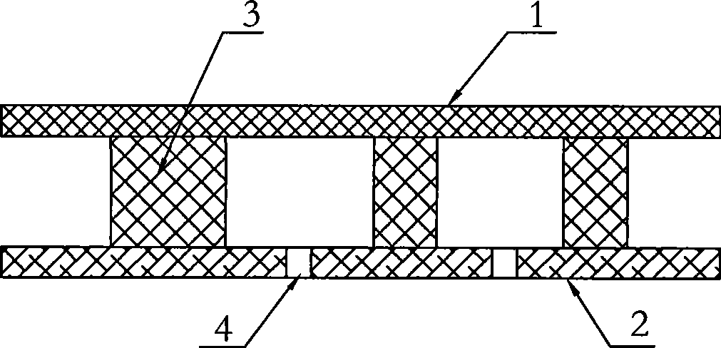
[0022] Embodiment 1: The multi-pole combined magnetic core, such as figure 1 As shown in the figure, it consists of a top plate 1, a bottom plate 2, and five magnetic core columns 3. Two threading holes 4 are arranged on the bottom plate 2. The magnetic core column 3 is an integral structure, and the magnetic core column 3 is fixed on the bottom plate 2. superior.

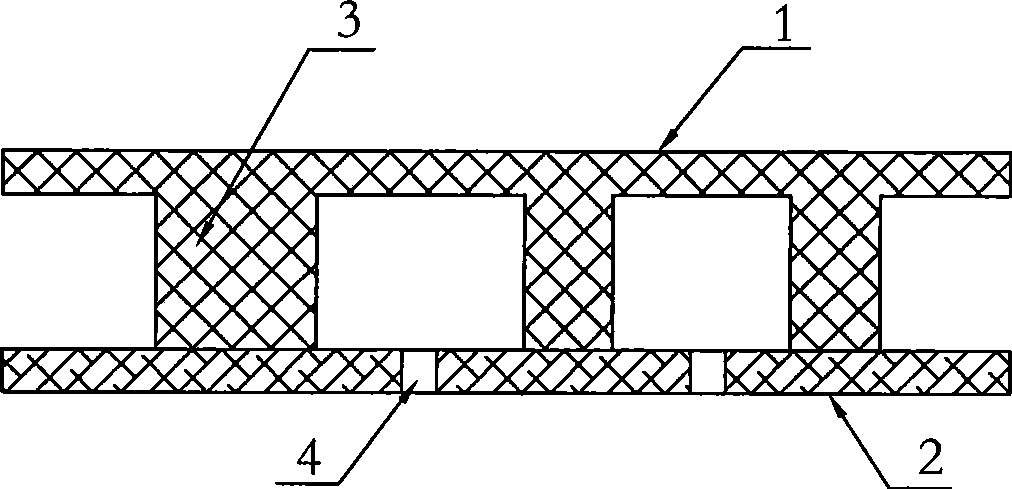
[0023] As a special case of Embodiment 1, the magnetic core column 3 is integrated with the top plate 1, such as figure 2 shown,

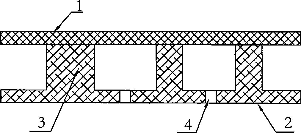
[0024] Or the core column 3 is integrated with the base plate 2, such as image 3 shown.

Embodiment 2

[0025] Embodiment 2: The multi-pole combined magnetic core, such as Figure 4 As shown in the figure, it consists of a top plate 1, a bottom plate 2, and five magnetic core columns 3. There are two threading holes 4 on the bottom plate. The magnetic core column 3 is a split structure, and the upper magnetic core column 31 is fixed on the top plate. 1. The upper and lower magnetic core columns 32 are fixed on the base plate 2.

[0026] As a special example of the second embodiment, the upper magnetic core leg 31 is integrated with the top plate 1 , and the lower magnetic core leg 32 is integrated with the bottom plate 2 .


PUM


Abstract

An assembled multi-polar magnetic core consists of a top plate, a bottom plate and a plurality of magnetic core columns, wherein all the magnetic core columns are arranged between the top plate and the bottom plate, and each magnetic core column is of a whole structure or a spilt structure; thread grooves are arranged on the bottom plate, and the number of the magnetic core columns can be arranged according to needs. As a plurality of magnetic circuits are assembled together and the spilt assembly structure is adopted, and all the magnetic core columns are arranged between the top plate and the bottom plate, the magnetic core with the assembled structure not only can optimize the distribution of the magnetic circuits, reduce the volume of electronic components, expand the functions of the electronic components and meet the requirements of miniaturization and multi-function of electronic devices, but also can improve the electromagnetic interference resistance capacity of the electronic components assembled together and reduce the electromagnetic interference generated by the electronic components to the outside simultaneously.

Description

Technical field: [0001] The present invention relates to a multi-pole combined magnetic core used for mounting multiple inductors, transformers or other electronic components. Background technique: [0002] With the rapid development of the electronic industry, high performance, miniaturization and multi-function are the future development directions of electronic equipment. Although the volume is reduced, there is a relatively large interference between the components, and the assembly is complicated, the cost is high, and the performance is not ideal. If multiple components with different functions with magnetic cores can be combined together, the assembly density of components can be increased, the volume can be reduced, the cost can be greatly reduced, and the electronic equipment can be further accelerated to the direction of high performance, miniaturization and multi-function. development speed. After searching, at present, there is no relevant report on this aspect...

Claims


Application Information

Patent Timeline
Patent Type & Authority Applications(China)
IPC IPC(8): H01F27/26H01F27/24H01F41/02
Inventor 董学娟
Owner 董学娟
Why Eureka
Try Eureka