
Shielding frame, shielding connector and connector assembly

A technology of connector components and connectors, which is applied to the parts, connections, and two-part connection devices of the connection device, etc., can solve the problems of limited anti-electromagnetic interference ability, inconsistency of upper and lower heights, and ground terminal contact, etc., so as to improve the anti-electromagnetic The ability to interfere, prevent electromagnetic leakage, and enhance the effect of fixation

Active Publication Date: 2021-04-09
CHINA AVIATION OPTICAL-ELECTRICAL TECH CO LTD
View PDF10 Cites 0 Cited by
  • Summary
  • Abstract
  • Description
  • Claims
  • Application Information

AI Technical Summary

Problems solved by technology

The shielding sheet is grounded to the printed board through several grounding terminals. However, after the grounding terminal is welded on the circuit board, the upper and lower heights are often inconsistent or due to the size error of the assembly operation, it cannot have a good contact with the grounding terminal.
The existing shielding frame is only set in the length direction of the insulator, and there is no shielding frame in the width direction of the insulator, so the ability to resist electromagnetic interference is limited

Method used


Image

  • Shielding frame, shielding connector and connector assembly
  • Shielding frame, shielding connector and connector assembly

Examples


Embodiment Construction

[0029] In order to further explain the technical means and effects of the present invention to achieve the intended purpose of the invention, the specific implementation, structure, characteristics and effects of the shielded connector proposed according to the present invention will be described below in conjunction with the drawings and preferred embodiments. Details are as follows.

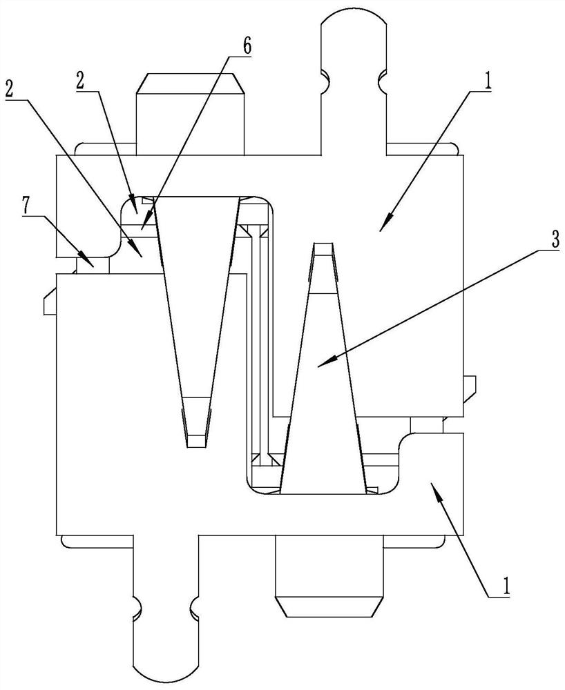
[0030] see figure 1 and figure 2 , which is a schematic diagram of the structure of each part of the shielded connector in Embodiment 1 of the present invention. The shielded connector includes an insulator 2 and a shielding frame 1 covering the outer periphery of the insulator. At least two elastic cantilevers 3 are arranged on the outside of the shielding frame 1. When connected When the connector is mated, the elastic cantilever 3 is in elastic contact with the outer wall of the shielding frame of the mating connector. The arrangement of the elastic cantilever 3 increases the insertion fo...


PUM


Abstract

The invention relates to a shielding frame, a shielding connector and a connector assembly, the shielding connector comprises an insulator and a shielding frame sleeving the periphery of the insulator, and the periphery of the shielding frame is provided with at least two elastic cantilevers used for making elastic contact with a shielding frame rigid base body of an adaptive connector. The design of the cantilevers on the two sides of the shielding frame improves the insertion force and separation force of the connector, so that the connector has good signal transmission performance in a strong vibration environment.

Description

technical field [0001] The invention belongs to the technical field of connectors, and in particular relates to a shielding frame, a shielding connector and a connector assembly. Background technique [0002] The particularity of the aerospace working environment determines that while high-speed electrical connectors are developing towards miniaturization and high density, it is necessary to improve their ability to resist various harsh working environments, such as electromagnetic interference and strong vibration. In existing connectors, a shielding sheet is provided outside the insulator, so as to improve the anti-electromagnetic interference capability of the connector. The shielding sheet is grounded to the printed board through a number of grounding terminals. However, after the grounding terminal is welded on the circuit board, the upper and lower heights are often inconsistent or due to the size error of the assembly operation, it cannot have a good contact with the ...

Claims


Application Information

Patent Timeline
IPC IPC(8): H01R13/6582H01R13/639H01R24/00
CPCH01R13/6582H01R13/639H01R24/00
Inventor 鲍小会李心宁张磊
Owner CHINA AVIATION OPTICAL-ELECTRICAL TECH CO LTD
Learn More