Electro-hydraulic combined braking system with electric power function and applicable to regenerative braking automobile

A technology of regenerative braking and electric power assist, applied in the direction of brake transmission, brakes, vehicle components, etc., can solve problems such as disadvantage, long pressure build-up time, increase system complexity and cost, and reduce manufacturing costs and pressure fluctuations. The effect of small size and high pressure regulation accuracy

Active Publication Date: 2014-10-29
南京经纬达汽车科技有限公司
View PDF6 Cites 30 Cited by
  • Summary
  • Abstract
  • Description
  • Claims
  • Application Information

AI Technical Summary

Problems solved by technology

Although all kinds of brake-by-wire systems have many advantages as mentioned above, they also have some disadvantages compared with non-wire-control systems: special failure backup devices need to be set up, which increases the complexity and cost of the system; Under certain conditions, the pedal force is always generated by the pedal stroke simulator, and the pedal force cannot be adjusted; the manpower applied to the brake pedal is not directly used to generate braking force, which is not conducive to shortening the brake action time
The electro-hydraulic composite braking system of the present invention overcomes two obvious deficiencies of the traditional power-assisted braking system: one is that active braking cannot be conveniently implemented; the other is that as long as the driver steps on the brake pedal, the friction brake will participate in generating braking force
The first deficiency of the power-assisted braking system makes it unable to meet the active braking needs of chassis active control systems such as anti-skid control (ASR), electronic stability control (ESC) and adaptive cruise control (ACC)
Although ESC vehicles equipped with ASR and differential pressure braking can implement active braking through the hydraulic control unit 31 of these active control systems, the pressure build-up time is relatively long, and because the electromagnetic valve is not suitable for long-term continuous work, it is difficult Meet the active supercharging needs of ACC and other control systems
The second deficiency of the booster braking system seriously hinders the braking energy recovery of new energy vehicles such as electric vehicles and hybrid vehicles

Method used


Image

  • Electro-hydraulic combined braking system with electric power function and applicable to regenerative braking automobile

Examples


Embodiment Construction

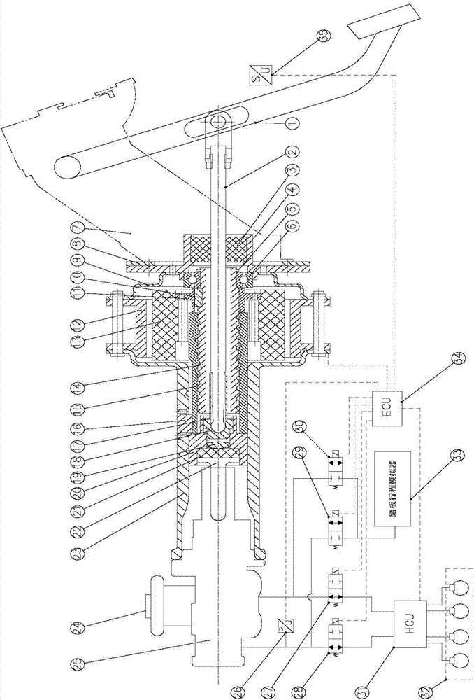
[0040] The present invention has the function of electric brake boosting and is applicable to the electro-hydraulic composite braking system with the regenerative braking function of automobiles, such as figure 1 As shown, it includes an electric brake booster device, a brake pedal assembly, a hydraulic control system, a sensor assembly, an electronic control unit 24 , and a pedal stroke simulator 33 .

[0041] The electric brake boosting device includes a hollow motor, a ball screw pair, a push plate 20 , a reaction plate 21 , a reaction plate push block 18 , and a push rod 22 .

[0042] Wherein, the front end and the rear end of the hollow motor are respectively fixed with a front end cover 23 and a rear end cover 9 by bolts; the front end cover 23 and the rear end cover 9 are fixed to the stator 12 of the hollow motor by bolts. There is an integrated sleeve on the front end cover 23; a through hole is opened in the center of the rear end cover 9; and the sleeve and the thro...


PUM


Abstract

The invention discloses an electro-hydraulic combined braking system with the electric power function and applicable to a regenerative braking automobile. A braking pedal pushes a piston ejector rod of a braking master cylinder to move through a pedal push rod, and an electric braking power device assists in pushing the ejector rod of the braking master cylinder to move. The structure of combining a ball screw pair with a reacting disc is adopted for the electric braking power device, and therefore the torque output by rotation of a motor can be converted into linear movement of an output rod. In the braking process, the movement of the piston ejector rod of the braking master cylinder can be braked by controlling rotation of the motor. According to received collection signals of all sensors on the automobile, an electronic control unit controls a hydraulic control system and the electric braking power device and selects one braking mode, and the braking modes include the electric power mode, the regenerative braking mode, and the driving braking mode. The electro-hydraulic combined braking system has the advantages of having the electric braking power and driving braking functions, and being high in reliability, low in manufacturing cost, small in pressure fluctuation and high in pressure adjusting accuracy.

Description

technical field [0001] The invention belongs to the technical field of automobile braking systems, and specifically relates to an electro-hydraulic composite braking system which has an electric power boosting function and is suitable for regenerative braking automobiles. Background technique [0002] As the core safety component of automobiles, the braking system has undergone several major changes and improvements. From the initial leather friction brakes to drum and disc brakes, to vacuum boosters, electric power boosters, anti-lock brake systems (ABS) and brake pedals used to reduce pressure adjustment when ABS intervenes Rebound center valve brake master cylinder etc. In recent years, the development of brake-by-wire systems (Brake-by-wire), such as electro-hydraulic brakes (EHB) and electro-mechanical brakes (EMB), has sprung up. [0003] At present, most automobile hydraulic braking systems use vacuum power assist, and a few cars use other forms of power assist devi...

Claims


Application Information

Patent Timeline
Patent Type & Authority Applications(China)
IPC IPC(8): B60T13/68B60T13/74
Inventor 邓伟文丁能根
Owner 南京经纬达汽车科技有限公司
Why Eureka
Try Eureka