Blowing rate adjusting device of railway vehicle

A rail vehicle and air volume technology, which is applied in the heating/cooling of railway vehicles, transportation and packaging, railway car body parts, etc., and can solve the problem that passengers cannot adjust the air outlet

Active Publication Date: 2014-10-29
CRRC QINGDAO SIFANG CO LTD
View PDF7 Cites 10 Cited by
  • Summary
  • Abstract
  • Description
  • Claims
  • Application Information

AI Technical Summary

Problems solved by technology

[0003] In order to improve the aesthetics of the entire carriage, the current air outlets are mostly hidden air outlets. The train air conditioning unit controls the temperature in the carriage through the feedback of the temperature sensor. However, this adjustment method is onl...

Method used


Image

  • Blowing rate adjusting device of railway vehicle
  • Blowing rate adjusting device of railway vehicle
  • Blowing rate adjusting device of railway vehicle

Examples


Embodiment 1

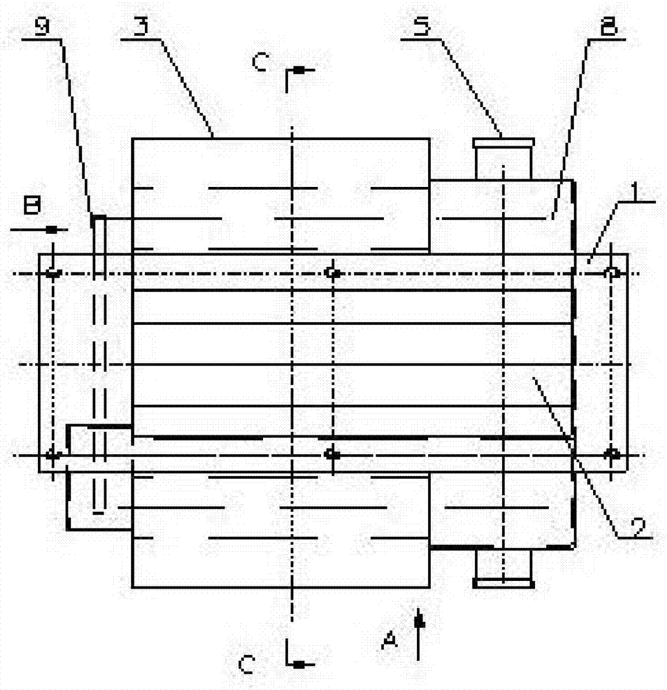
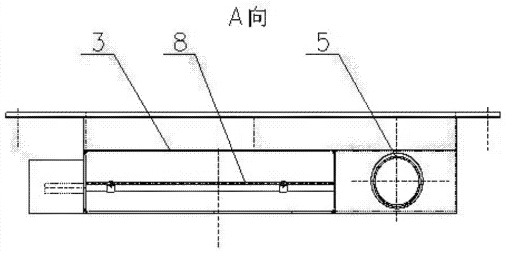
[0023] Such as figure 1 and figure 2 As shown, the present invention provides a rail vehicle air volume adjustment device, comprising a tuyere body 1, at least one air inlet 2 and an air outlet 3 are opened on the tuyere body 1, and the air inlet 2 is opened on the top of the tuyere body 1 and the air conditioning unit. The air supply duct (not shown in the figure) is connected, and the air supply duct is arranged along the longitudinal length of the car body. The air outlet 3 is sent into the compartment to adjust the ambient temperature in the compartment.

[0024] For high-grade trains equipped with independent private rooms such as soft sleepers, air outlets 3 are provided in each private room. In this embodiment, the air outlet body 1 is arranged longitudinally or transversely along the car body, and is symmetrically arranged on both sides of the air outlet body 1. There are two air outlets 3, and the air processed by the air conditioning unit flows out from the air ou...

Embodiment 2

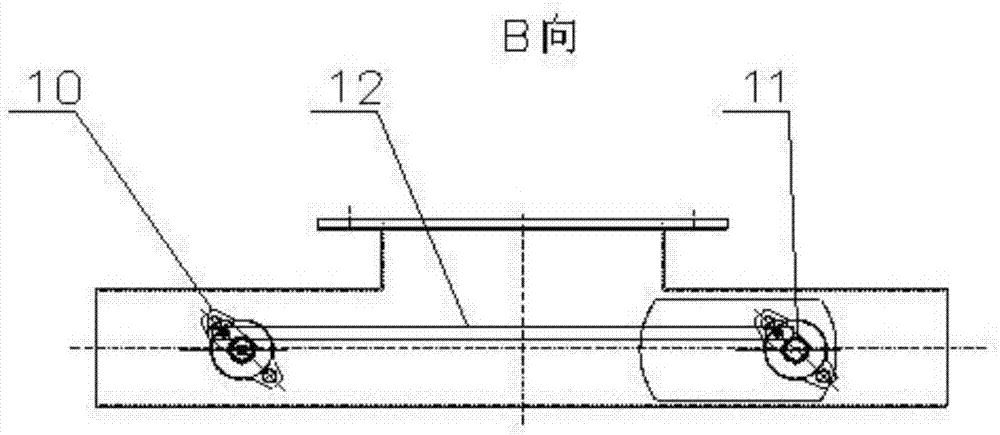
[0032]The difference from Embodiment 1 is that when the area of ​​the private room is large and the distance between the two air outlets 3 is relatively far, or when the two air outlets 3 are correspondingly installed in different private rooms, the symmetrically arranged two air outlets 3 They are not connected through the link mechanism 9, but are independently controlled. Each rotating shaft 8 is connected to a stepping motor, and each air outlet 3 can be provided with a set of control devices for independent control. Other structures and control methods are the same as in Embodiment 1. same.

Embodiment 3

[0034] The difference from Embodiment 1 is that each compartment is provided with an air outlet 3, the air outlet body 1 is no longer provided with a deflector 4, and a bypass air outlet 5 is provided next to the air outlet 3. Other structures and control methods Same as Embodiment 1.


PUM


Abstract

The invention relates to a blowing rate adjusting device of a railway vehicle. The blowing rate adjusting device of the railway vehicle comprises an air opening body. At least one air inlet and one air outlet are formed in the air opening body. Each air inlet is connected with an air supply duct of an air conditioner unit. A first air guide blade is arranged at the position of each air outlet. At least one bypass air outlet is further formed in the air opening body. Each bypass air outlet is connected with a return air duct of the air conditioner unit. A second air guide blade is arranged at the position of each bypass air outlet. Each first air guide blade and the corresponding second air guide blade are connected through a linkage mechanism. Each linkage mechanism is connected with an executing mechanism. Each executing mechanism is connected with a control device. According to the blowing rate adjusting device of the railway vehicle, the air outlet volume of each air outlet is controlled by a passenger through a control panel according to the demand of the passenger, so that the temperature of a room is changed according to the blowing rate, and therefore the person sense demand is met; in addition, it is avoided that the blowing rate of the adjacent air outlet is changed accordingly.

Description

technical field [0001] The invention relates to a rail vehicle air supply mechanism, in particular to a rail vehicle air volume adjusting device, which belongs to the technical field of rail vehicle air supply. Background technique [0002] Today, with the development of science and technology, the design ideas of rail vehicles are increasingly developing in the direction of humanization, comfort and automation. The air outlet body of the existing train is mostly installed above the roof plate in the car. The air outlet body has an air inlet and an air outlet. The air deflector that adjusts the air volume of the air outlet, and the air inlet is connected to the air outlet of the indoor unit of the air conditioner through the air supply duct, and the air treated by the air conditioner enters the air supply duct from the exhaust outlet of the indoor unit of the air conditioner, Enter the air inlet body from the air inlet of the air outlet body, and finally discharge into the ...

Claims


Application Information

Patent Timeline
IPC IPC(8): B61D27/00F24F11/04
Inventor 于大伟李春峰刘振环王建军王冰松程建峰
Owner CRRC QINGDAO SIFANG CO LTD
Why Eureka
Try Eureka