Automatic sand feeding apparatus

An automatic sand filling and sand storage technology, which is applied in metal processing equipment, casting molding equipment, cleaning/processing machinery of casting mold materials, etc., can solve the problems of fast sand dropping, loose sand, and high labor intensity, and achieve Convenient control, uniform sand discharge, and improved production efficiency

Inactive Publication Date: 2014-11-05
兴化市振南合金机械有限公司
View PDF6 Cites 4 Cited by
  • Summary
  • Abstract
  • Description
  • Claims
  • Application Information

AI Technical Summary

Problems solved by technology

[0003] In the actual operation process, we are likely to encounter two problems. The first is the uniformity of sanding. The traditional sanding method is manual addition. Humans use shovels to add sand to the mold sandbox based on their work experience. This is not only labor-intensive. , and it is not easy to control the amount of sand around the sandbox. Even if the vibration table is used for three-dimensional vibration, it is difficult to ensure that the amount of sand around the foam plastic model is uniform, especially when encountering casting models with strange shapes. Or the sunken position, it is more prone to the problem that the sand is not compact
There are also some manufacturing companies that use heightened sand storage bins and use the method of adding sand to the inverted conical discharge port. Although this method liberates manpower to a certain extent, it also brings other inconvenience. First of all, due to the discharge The opening is set directly below the sand storage bin. Due to gravity, the speed of sand dropping will be very fast and difficult to control. Even if a high-speed vibrating table is used, the shaking speed is far behind the speed of sand loading and unloading, and the sand body cannot be compressed. The compaction problem still exists
[0004] Moreover, due to the diversity of processed products in actual operation, it is often necessary to perform sanding operations on several boxes in one batch. The traditional sanding machine is difficult to adjust because of its fixed installation and shape, and it can work with multiple sandboxes.
Especially now that many castings are of different sizes, it is difficult to use one type of sandbox at one time. How to make the traditional sanding machine adapt to a variety of sandboxes of different sizes has also become a challenge for many alloy casting companies to liberate their labor force. Issues to Consider in Improving Production Efficiency

Method used


Image

  • Automatic sand feeding apparatus
  • Automatic sand feeding apparatus

Examples


Embodiment Construction

[0017] The technical solution will be described in detail below through a best embodiment, but the protection scope of the present invention is not limited to the embodiment.

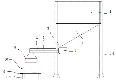
[0018] refer to figure 1 As shown, an automatic sand adding device includes a sand storage box 1, a feeding port 3 and a mold sand box 10, and a quicksand chute 2 is arranged at the lower end of the sand storage box 1.

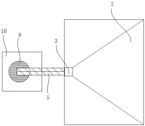
[0019] refer to figure 1 and figure 2 As shown, the discharge port 3 is arranged on the side of the sand storage box 1 close to the mold sand box 10 . The lower end of the discharge port 3 is provided with a conveying pipeline 5, and a sand inlet is arranged on the conveying pipe 5 to connect with the discharge port 3, and the discharge port 3 and the conveying pipe 5 are connected by a plane ring. A helical blade 7 is arranged in the conveying pipe 5 .

[0020] refer to figure 1 As shown, the delivery pipe 5 is provided with a drive motor 6 at one end close to the plane ring.

...


PUM


Abstract

The invention discloses an automatic sand feeding apparatus. The apparatus comprises a sand storage box, a blanking hole and a die sand box, the lower end of the sand storage box is provided with an inclined sand flow channel, the blanking hole is arranged at one side of the sand storage box close to the die sand box, the lower end of the blanking hole is provided with a conveying pipeline, the conveying pipeline is provided with a sand feeding hole abutted to the blanking hole, and the blanking hole is connected with the conveying pipeline through a planar ring. A spiral blade is arranged in the conveying pipeline, and one end of the conveying pipeline close to the planar ring is provided with a driving motor. The conveying pipeline of the apparatus can freely veer on the planar ring, so the production efficiency is greatly improved. The apparatus adopts the motor to drive the helical blade in order to carry out sand conveying in the conveying pipeline, so the sand conveying rate can be controlled, and the conveying efficiency of the conveying pipeline can be conveniently controlled only through controlling the rotating speed of the motor.

Description

technical field [0001] The invention relates to a manufacturing equipment of alloy castings, more specifically, relates to a device for automatically adding sand in the process of manufacturing alloy castings. Background technique [0002] At present, the traditional alloy manufacturing industry still relies heavily on forming molds, and qualified products must be qualified molds, and various types of sandboxes will also be used. Its main manufacturing process is as follows. First, draw the 1:1 ratio mold drawing of the product according to the demand, make the foam board into an equal-scale foam plastic model, coat and hang special high-temperature-resistant materials, put it into the mold sandbox, and then use vibration The method of sand filling is used to compact and compact the surroundings of the mold model. After the dry sand is compacted and formed, the molten metal is injected to vaporize the foam plastic model to obtain a metal casting in proportion to the molten ...

Claims


Application Information

Patent Timeline
Patent Type & Authority Applications(China)
IPC IPC(8): B22C5/12
Inventor 金晓彬
Owner 兴化市振南合金机械有限公司
Why Eureka
Try Eureka