Method and device for obtaining volume leakage speed under standard condition of gas well

A leak rate and volume technology, applied in earthmoving, wellbore/well components, measurement, etc., can solve problems such as volume leak rate under the standard conditions of gas wells that cannot be determined

Active Publication Date: 2014-11-05
PETROCHINA CO LTD
View PDF5 Cites 20 Cited by
  • Summary
  • Abstract
  • Description
  • Claims
  • Application Information

AI Technical Summary

Problems solved by technology

[0006] In order to solve the problem that the existing technology cannot determine the volumetric leakage rate under the standard gas well condition, the present invention proposes a method and device for obtaining the volumetric leakage rate under the gas well standard condition, using the conventional basic data of the gas well, and taking the small hole leakage model of the surface gas transmission pipeline as the Based on the principle of integration, the leakage area of ​​the downhole annular space of the gas well is determined, and the volume leakage rate and leakage area under standard conditions are realized.

Method used


Image

  • Method and device for obtaining volume leakage speed under standard condition of gas well
  • Method and device for obtaining volume leakage speed under standard condition of gas well
  • Method and device for obtaining volume leakage speed under standard condition of gas well

Examples


Embodiment

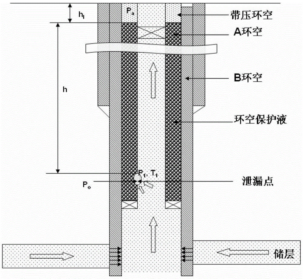
[0095] Taking well XX-1 in XX gas field as an example, as image 3 As shown, it is a schematic diagram of the gas well leakage model of this embodiment, in which the representative meanings of each parameter are marked.

[0096] (1) Determine the depth of the leak point;

[0097] Such as Figure 4 Shown is the pressure recovery curve of the annulus pressure relief of well XX-1 in this embodiment. It is necessary to determine the stable stage of annular pressure balance according to this curve, and then determine the depth of the annular leakage point. According to the basic data of the gas well and the pressure relief data of the casing annulus, the equilibrium annular pressure is determined, and the Hagedorn-Brown method is used to calculate the temperature and pressure profile of the gas well. When well XX-1 is depressurized and balanced, the wellhead annular pressure is 34710000MPa; when the pressure is restored to balance, that is, the pressure inside and outside the tu...


PUM


Abstract

The invention relates to a method and a device for obtaining the volume leakage speed under the standard condition of a gas well, wherein the method comprises the following steps that: the depth of a leakage point, the gas pressure at the leakage point in an oil pipe and the corresponding temperature are obtained according to a condition that the annular pressure in the position of the leakage point under the well is balanced with the pressure in the oil pipe; the flowing state of the leakage is judged according to the gas pressure at the leakage point in the oil pipe and the annular pressure in the position of the leakage point in different moments; a mass leakage speed expression in the position of the leakage point is converted to obtain a volume leakage speed expression in the position of the leakage point; the volume leakage speed expression in the position of the leakage point is subjected to time integration to obtain a volume leakage speed expression in the position of the leakage point in the corresponding time; the leakage area of the position of the leakage point in the corresponding time is obtained; the leakage area of the position of the leakage point in any pressure relief time period is determined according to the volume leakage speed in the position of the leakage point; and the volume leakage speed of the gas well oil jacket annular leakage gas under the standard condition is obtained according to the leakage area of the position of the leakage point in any pressure relief time.

Description

technical field [0001] The invention relates to the technical field of gas recovery engineering, in particular to a method and device for obtaining volume leakage rate under standard gas well conditions. Background technique [0002] At present, with the continuous development of natural gas exploration and development, a large number of high-temperature, high-pressure, acidic medium gas wells have been put into trial production or put into production, and the ensuing gas well integrity problems have become increasingly prominent. The integrity requirement of a gas well is to ensure that uncontrolled overflow of subsurface fluids does not occur through management and technical means during the entire life. In the event of an integrity failure, the downhole natural gas will enter the oil casing annulus, that is, the annulus is under pressure, and the severe case may lead to abnormal pressure in the annulus, and even cause downhole natural gas to leak to the ground and explode...

Claims


Application Information

Patent Timeline
Patent Type & Authority Applications(China)
IPC IPC(8): E21B47/10
Inventor 王云李文魁李隽曹光强
Owner PETROCHINA CO LTD
Why Eureka
Try Eureka