
a revolving lantern

A revolving lamp and lampshade technology, which is applied to lampshades, special patterns, decorative arts, etc., can solve the problems of inability to present the revolving lamp effect, damage to the lampshade or the wall of the revolving cylinder, inconvenient installation of the revolving cylinder and thermal light source, etc. The effect of high safety and convenient operation

Inactive Publication Date: 2016-03-02
周松林
View PDF5 Cites 0 Cited by
  • Summary
  • Abstract
  • Description
  • Claims
  • Application Information

AI Technical Summary

Problems solved by technology

[0002] At present, Chinese traditional festivals often use revolving lanterns in order to create a festive atmosphere, but traditional revolving lanterns use the rising thermal airflow generated by the heat source that can generate heat and light inside the revolving drum. The blades exert a thrust, so that the blades are forced to drive the entire drum to rotate along the central axis of the drum. However, because the lamp holder of the existing revolving lantern is fixed, it is not convenient to install the drum and heat inside it. The light source, and it is also very easy to cause damage to the lampshade or the wall of the drum during the installation process, resulting in the inability to show the effect that the revolving door should have.

Method used

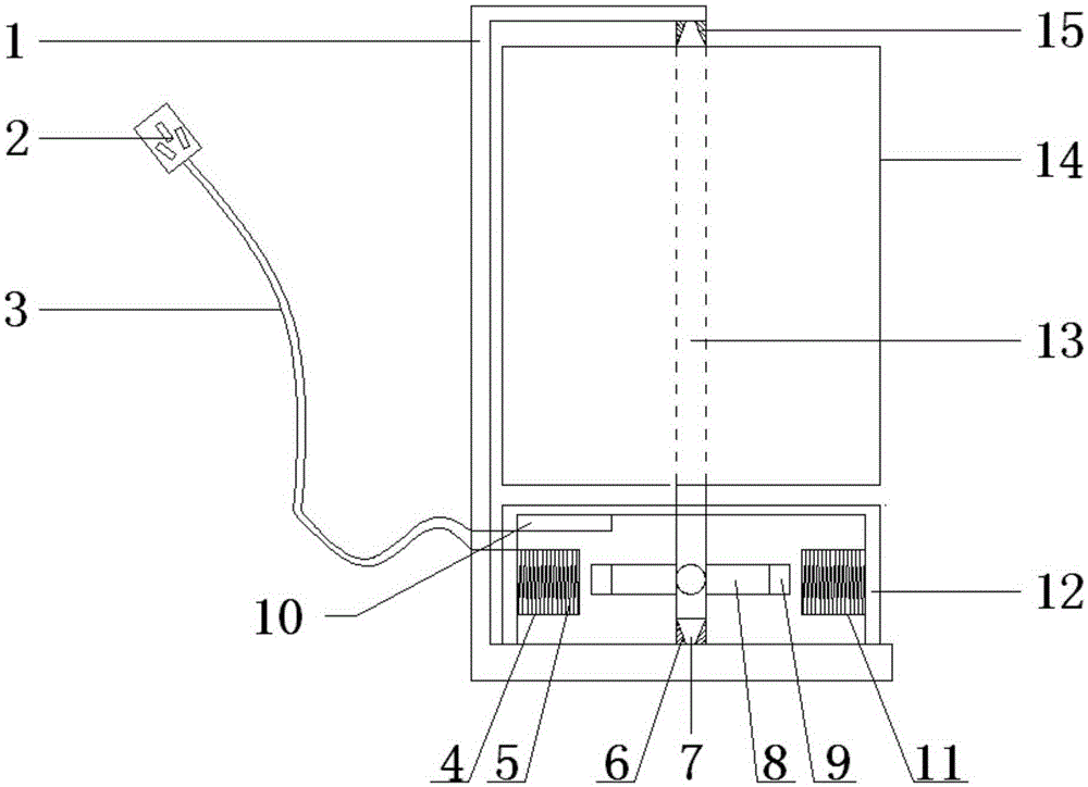

Image

  • a revolving lantern

Examples


Embodiment Construction

[0015] The principles and features of the present invention are described below in conjunction with the accompanying drawings, and the examples given are only used to explain the present invention, and are not intended to limit the scope of the present invention.

[0016] like figure 1 As shown, a revolving lantern comprises a first bracket 1, a second bracket 12, a cross holder 9, a lampshade 14, a rotating shaft 13, a magnet 9, an electromagnetic induction coil 5 and a commutator 10, and the first bracket 1 and the The second brackets 12 are C-shaped, and the first bracket 1 is a side opening, the second bracket 12 is located in the side opening of the first bracket 1, and the opening is downward, the first bracket 1 Two brackets 12 open downwards and are fixed on the inner side of the bottom end of the first bracket 1, and the center position of one side away from the opening direction of the second bracket 12 is provided with a through hole matching the diameter of the rot...


PUM


Abstract

The invention relates to a trotting horse lamp. The trotting horse lamp comprises a first support, a second support, a cross fixing frame, a lampshade, a rotary shaft, magnets, electromagnetic induction coils and a reverser. The cross fixing frame is arranged in the second support. Four end frames of the cross fixing frame are provided with the magnets respectively. The inner sides of the two ends of the second support are provided with a first coil fixing key and a second coil fixing key respectively. The first coil fixing key and the second coil fixing key are matched with the magnets, are symmetrical to each other and are wound with the electromagnetic induction coils. The electromagnetic induction coil on the first coil fixing key and the electromagnetic induction coil on the second coil fixing key are connected to the positive electrode and the negative electrode of a socket respectively through wires in an extending mode. The trotting horse lamp has the advantages that the electromagnetic induction coils drive the magnets fixed to the cross fixing frame to operate through electromagnetic induction by combination with the reverser, the cross fixing frame drives the rotary shaft to operate, then the lampshade operates to reflect an animation effect, safety is high, the structure is simple, and operation is convenient.

Description

technical field [0001] The invention relates to the field of lamps, in particular to a revolving lantern driven by electromagnetic induction to move a rotating shaft. Background technique [0002] At present, Chinese traditional festivals often use revolving lanterns in order to create a festive atmosphere, but traditional revolving lanterns use the rising thermal airflow generated by the heat source that can generate heat and light inside the revolving drum. The blades exert a thrust, so that the blades are forced to drive the entire drum to rotate along the central axis of the drum. However, because the lamp holder of the existing revolving lantern is fixed, it is not convenient to install the drum and heat inside it. The light source, and it is also very easy to cause damage to the lampshade or the wall of the drum during the installation process, resulting in the inability to show the desired effect of the revolving lantern. Therefore, how to design a kind of revolving ...

Claims


Application Information

Patent Timeline
Patent Type & Authority Patents(China)
IPC IPC(8): F21S10/00F21V3/04F21V14/00F21W121/00
Inventor 周松林
Owner 周松林
Learn More