
Concentric winding field coil making tool

A technology of excitation coils and concentric windings, which is applied in the direction of electromechanical devices, electric components, and manufacturing motor generators, etc., can solve the problems of difficult forming of the end of the excitation coil of concentric windings, and achieve easy shaping of the ends, regular forming, and embedding of wires high quality effect

Inactive Publication Date: 2014-11-05
CSR CHENGDU
View PDF6 Cites 0 Cited by
  • Summary
  • Abstract
  • Description
  • Claims
  • Application Information

AI Technical Summary

Problems solved by technology

[0004] The object of the present invention is to provide a concentric winding excitation coil production tool for the above existing problems, which can solve the problem of difficult formation of the end of the concentric winding excitation coil of the generator rotor

Method used


Image

  • Concentric winding field coil making tool
  • Concentric winding field coil making tool

Examples


Embodiment

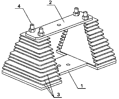
[0015] Such as figure 1 As shown, a concentric winding excitation coil manufacturing tooling includes a lower plate 1 and an upper plate 2, two stacks of coils 3 are arranged symmetrically at both ends between the two plates, and two bolts and nuts 4 are used to connect the lower plate from bottom to top. The plate 1, the coil 3 and the upper plate 2 are fastened, and each coil 3 is divided into three coil layers, the length of these three coil layers is the same, and the width dimension changes in steps.

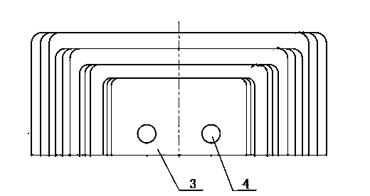
[0016] In this embodiment, the width of each coil layer of each stack of coils 3 becomes shorter successively from bottom to top, as figure 2 shown.

[0017] Each stack of coils 3 is composed of four coils.


PUM


Abstract

The invention discloses a concentric winding field coil making tool. The concentric winding field coil making tool comprises a lower plate and an upper plate, wherein two coils are symmetrically arranged at the two ends of the portion between the two plates respectively, the lower plate, the coils and the upper plate are fastened through two bolts and two nuts from bottom to top, each coil is divided into three coil layers, the corresponding three coil layers are the same in length, and the widths of the corresponding three coil layers change in a stepped mode. The concentric winding field coil making tool has the advantages that wire insertion can be convenient to perform when the coils are made, shaping of ends is easy to perform, the coils are shaped regularly, the requirement of assembly can be met, and quality of wire insertion is high.

Description

technical field [0001] The invention relates to the technical field of alternators, in particular to a manufacturing tool for concentric winding excitation coils. Background technique [0002] When the alternator rotor uses concentric windings as excitation coils, the traditional coil manufacturing process scheme will lead to the shape of the coil ends being too thick and concentrated, and it will be a technical problem to obtain regular shaped ends during the wire embedding process. [0003] Due to the influence of the ends, it is difficult to insert the wires. The enameled wires at the four ends of the coil (the connection transition part of the two effective sides of the coil) are too concentrated, it is difficult to arrange them evenly in a limited space, and it is difficult to form the ends. Assembly requirements cannot be met. At the same time, the enameled wire paint film is easily damaged, which affects the inter-turn insulation performance of the winding. Content...

Claims


Application Information

Patent Timeline
Patent Type & Authority Applications(China)
IPC IPC(8): H02K15/04
Inventor 付星熊燕高云霞唐怀路孙娟娟
Owner CSR CHENGDU
Learn More