
Magnetic field modulation AC brushless doubly-fed motor

A technology of doubly-fed motor and magnetic field modulation, applied in AC motor control, control system, electrical components, etc., can solve the problems of low power density, unstable motor torque, large noise and vibration, etc., to improve output power and reduce noise. , the effect of reducing loss

Pending Publication Date: 2020-05-15
GUANGDONG SHANGSHUI ENERGY TECH
View PDF0 Cites 0 Cited by
  • Summary
  • Abstract
  • Description
  • Claims
  • Application Information

AI Technical Summary

Problems solved by technology

Among the two rotor structures, the reluctance rotor has less rotor loss and higher efficiency because there is no conductor on the rotor, but the disadvantage is that the noise and vibration are relatively large, and the "concentric cage" rotor has better starting characteristics as a motor, but among them The winding conductor needs to be isolated from the iron core with insulating material, the manufacturing process is complicated, and there are many problems such as low power density.
The modulated alternating current contains a large number of harmonics. By increasing the PWM chopping frequency, the chopping frequency can be adjusted to 20KHz, so that the high-frequency noise is in the ultrasonic region, making it impossible for the human ear to distinguish, thereby achieving the purpose of reducing noise, but increasing the chopping frequency The frequency will cause the torque of the motor to be unstable, and there is a risk of out of step

Method used


Image

  • Magnetic field modulation AC brushless doubly-fed motor
  • Magnetic field modulation AC brushless doubly-fed motor
  • Magnetic field modulation AC brushless doubly-fed motor

Examples


Embodiment Construction

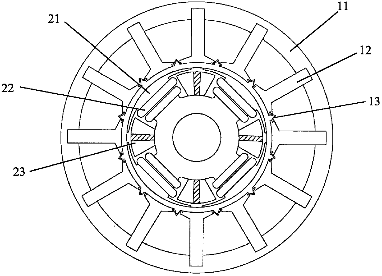
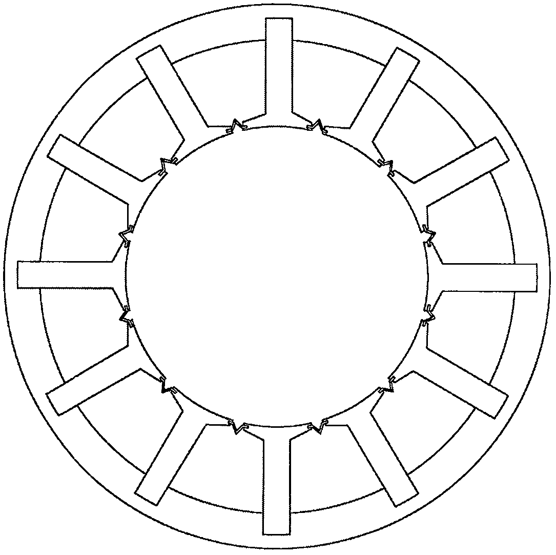
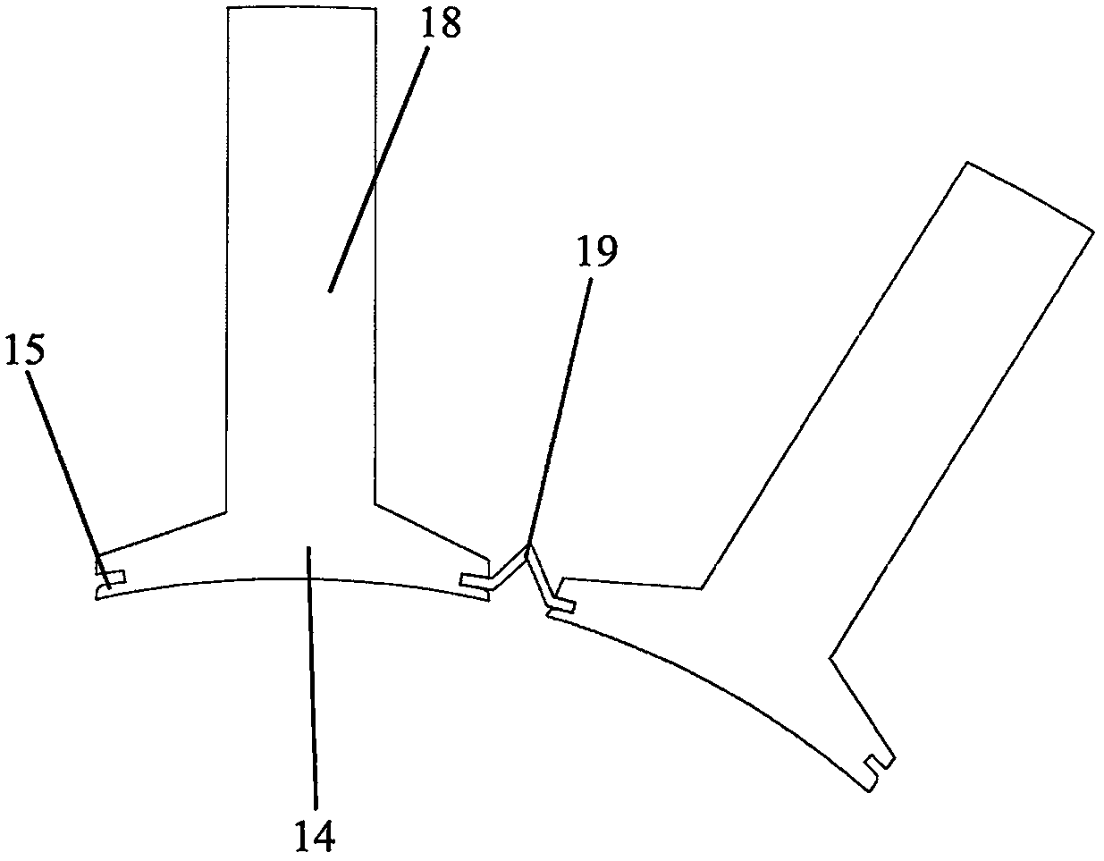
[0029] The following will clearly and completely describe the technical solutions in the embodiments of the present invention with reference to the accompanying drawings in the embodiments of the present invention. Obviously, the described embodiments are only some, not all, embodiments of the present invention. Based on the embodiments of the present invention, all other embodiments obtained by persons of ordinary skill in the art without making creative efforts belong to the protection scope of the present invention.

[0030] see figure 1 As shown, the present invention discloses a magnetic field modulation AC brushless doubly-fed motor. The stator includes a stator yoke 11, detachable stator teeth 12 arranged inside the stator yoke 11, and a magnet set between the stator teeth 12. The insert 13; the stator tooth 12 has an umbrella-shaped end 14, and the two sides of the umbrella-shaped end 14 are symmetrically provided with insertion slots 15; the magnetic insert 13 is inse...


PUM

PropertyMeasurementUnit
polar arc coefficientaaaaaaaaaa

Abstract

The invention discloses a magnetic field modulation AC brushless doubly-fed motor which comprises a stator and a rotor. The stator comprises a stator yoke part, stator teeth which are detachably arranged at the inner side of the stator yoke part, and magnetic insertion sheets which are arranged between the stator teeth. Each stator tooth is provided with an umbrella-shaped end part, and insertinggrooves are symmetrically formed at the two sides of each umbrella-shaped end part. The magnetic inserting pieces are inserted into the inserting grooves of the two adjacent stator teeth, and V-shapedparts sunken towards the stator yoke part are arranged between the magnetic inserting pieces. The rotor comprises rotor teeth, and a self-closing coil is wound on each rotor tooth. A magnetic conductive block is inserted between every two adjacent rotor teeth, and an insulator is arranged at the central axis position of the magnetic conductive block. According to the invention, a slotless structure is formed by additionally arranging the magnetic inserting sheets between the stator teeth, and by adding the magnetic conductive blocks, the magnetic adjusting capability of the rotor is enhanced,so that the modulation of a magnetic field is realized, the noise of the brushless motor is reduced, and the loss is reduced.

Description

technical field [0001] The invention relates to the technical field of motors, in particular to a magnetic field modulation AC brushless double-fed motor. Background technique [0002] The brushless doubly-fed motor is powered by grid power and variable frequency power supply separately. It has the characteristics of reliable operation, requires a small capacity of variable frequency power supply, and can adopt different voltage levels. , used for wind power or hydraulic variable speed constant frequency power generation, etc. [0003] The key to good performance of brushless doubly-fed motors is the rotor. Among them, the rotor type can be divided into reactive type and inductive type. There are mainly two types of specific rotor structures. One is the reluctance rotor belonging to the reactive type. The rotor core is made into a structure similar to a salient pole without any conductors on it; One is an inductive "concentric cage" rotor, in which a plurality of ring-cage...

Claims


Application Information

Patent Timeline
Patent Type & Authority Applications(China)
IPC IPC(8): H02K1/24H02K1/12H02P27/02
CPCH02K1/12H02K1/24H02P27/02
Inventor 杨华
Owner GUANGDONG SHANGSHUI ENERGY TECH
Learn More