Superconducting air vacuum tube

A vacuum tube and air technology, which is applied in the field of solar energy, can solve the problems of reducing the heat absorption of the heat absorption tube, difficult sealing, and long heating time.

Inactive Publication Date: 2009-10-21
董宜昌
View PDF1 Cites 0 Cited by
  • Summary
  • Abstract
  • Description
  • Claims
  • Application Information

AI Technical Summary

Problems solved by technology

[0002] In superconducting solar heat absorbing tube technology, the idea is good, but it violates the working principle of thermodynamics. 99221421.1 fills the superconducting liquid at the bottom of the inner tube of the solar heat absorbing tube. The design of this superconducting solar heat absorbing tube solves the problem. The conventional problem of frozen tubes and fried tubes existing in the existing water-filled solar heat absorbing tubes and the difficulty of sealing due to different expansion coefficients of heat pipes, high processing costs, and low yield of easily broken products have been solved. The conductive liquid is at the bottom of the tube, and the liquid is heated in the upper part of the heat collecting tube. Only when the temperature of the upper part is higher than the vaporization temperature of the superconducting liquid, the superconducting liquid will vaporize and transfer heat. Due to the weak solar radiation in winter, the heating time is very long , can not achieve the purpose of rapid heating, but reduces the heat absorption of the heat-absorbing tube, the market development has not only not been recognized by consumers, but also the market has gone extinct

Method used


Image

  • Superconducting air vacuum tube
  • Superconducting air vacuum tube
  • Superconducting air vacuum tube

Examples


Embodiment Construction

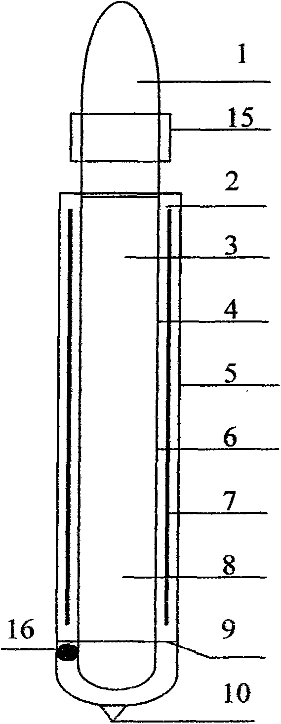
[0008] In specific embodiment 1, the condensation end (1) of the superconducting air vacuum tube is connected to the power generation module (15), the vacuum tube (2) is connected to the superconducting air vacuum tube (3), and the inner glass tube (4) is connected to the outer glass tube (5). ) Is connected at one end, the heat-absorbing coating (6) is applied to the surface of the inner glass tube (4), and the built-in condensing reflector (7) is installed between the inner and outer glass tubes (4, 5) and close to the outer glass tube On one side of (5), the spring bracket ((9), getter (16) and the outer glass tube (5) bridge the middle bottom of the inner glass tube (4), and one end of the outer glass tube (5) is welded to the vacuum sealing nozzle (16) , The heat-conducting air (8) is sealed in the superconducting air vacuum tube (3).

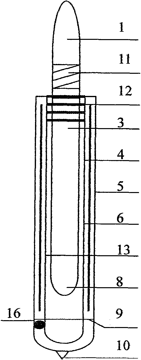
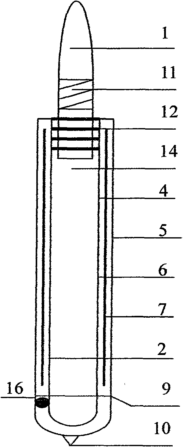
[0009] In the specific embodiment 2, the superconducting air vacuum tube (3) and the inner tube of the vacuum tube (2) are connected through ...


PUM


Abstract

A superconducting air vacuum tube comprises an external glass tube, an internal glass tube, a heat absorbing coating, a getter, a spring bracket and evacuated sealing and is characterized by newly adding a superconducting air vacuum tube spring bracket, a glass (metal) superconducting air vacuum tube with sealing at one end or two ends, a condensation end connecting screw, a superconducting air vacuum tube connecting sealing ring, an internal condensation light reflector plate and an electricity-generating module. Compared with superconductor solar heat absorption tubes and heat tubes, the superconducting air vacuum tube has seven advantages as below: 1. changing working principle, carrying out direct heat transfer, having no vaporization time and increasing heat-collecting capacity; 2. simplifying production process and increasing productivity ratio; 3. having simple structure, integral and separated production and convenient manufacturing, being free from equipment limit; 4. adopting internal condensation light to make up deficiency of solar radiation amount in winter; 5. ensuring heating bodies free from limit of fixed sizes, facilitating intercalation of the electricity-generating module and reducing generating cost of the module; 6. lowering process cost of tube manufacture and facilitating popularization; 7. being free of freezing below -500 degrees Celsius and facilitating popularization.

Description

Technical field: [0001] The invention relates to a solar superconducting air vacuum heat absorption tube, which belongs to the field of solar energy. technical background: [0002] In the superconducting solar heat absorption tube technology, the idea is good, but it violates the working principle of thermodynamics. 99221421.1 fills the superconducting liquid at the bottom of the inner tube of the solar heat absorption tube. The design of this superconducting solar heat absorption tube is solved The conventional problems of frozen pipes and explosive pipes in the existing water-injected solar heat-absorbing pipes and the different expansion coefficients of heat pipes are difficult to seal, high processing costs, easy to break and low yield. However, the superconducting solar heat-absorbing pipes are due to superconducting solar heat-absorbing pipes. The guiding liquid is at the bottom of the tube, and the liquid is heated in the upper part of the heat collecting tube. Only when t...

Claims


Application Information

Patent Timeline
Patent Type & Authority Applications(China)
IPC IPC(8): F24J2/46F24J2/48
CPCY02E10/40
Inventor 董宜昌赫艳春
Owner 董宜昌
Why Eureka
Try Eureka